
We have both software and firmware, each running on different devices and each with their own purpose. The software lives on the RaspberryPi development board and controls the entirety of the system. The RaspberryPi is meant to replace a full laptop and is the only user-facing portion of our system. The firmware lives on the STM32 microcontroller which lives on our custom PCB. Its only job is to run the CCD and communicate the data back to the RaspberryPi.
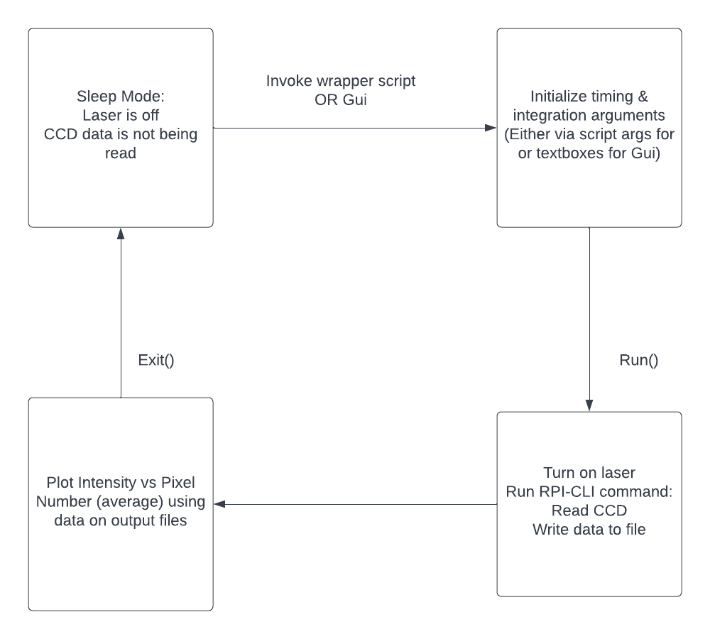
Our software has four primary states shown on the left. We start in the sleeping state to avoid unnecessary power consumption. On wake, the system allows the user to set timing and integration values before running. The RaspberryPi will turn on the laser, power the PCB, and send over SPI, using the Ottery-CLI, the timing and integration values to the PCB firmware. The firmware will send CCD data back to the RaspberryPi, which will automatically be written to a file. The RaspberryPi will do some signal processing and output a plot of intensity by pixel number to the user. Upon completion of the run, the RaspberryPi will disconnect power from the PCB and go into sleep mode.