
All molecules have a natural resonance frequency at which they vibrate, and when we hit these molecules with light, they sometimes move become energized (ie move to a higher energy state). When these molecules goes back to their initial energy state, they release the extra energy as a photon that is of a different wavelength and energy of the incident photon. This difference in their energies is known as the Raman shift, and can be calculated. Given the incident wavelength and the molecule, we can calculate the Raman shift and set up a system to specifically detect photons of this energy.
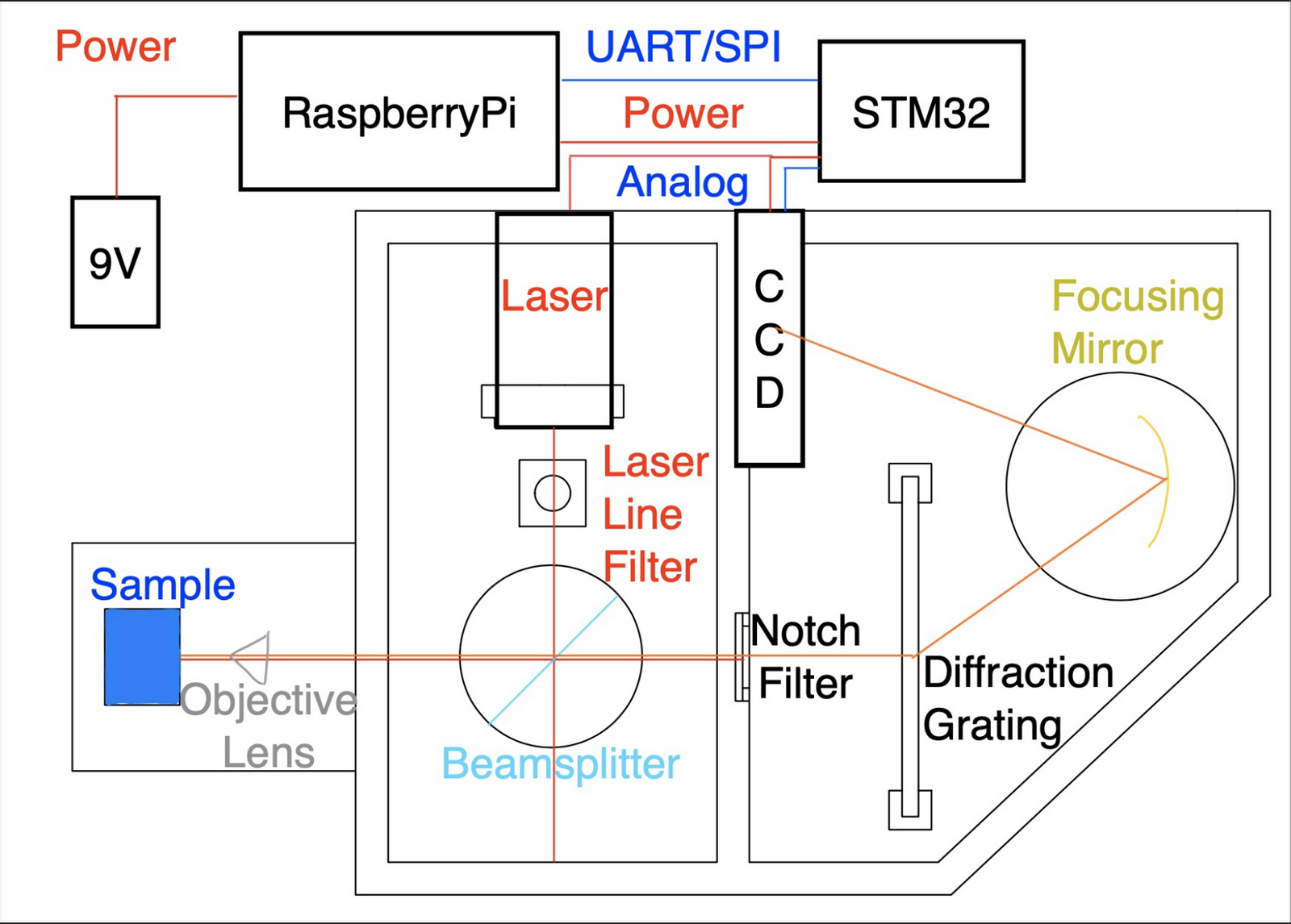
The above is a diagram drawn on top of the CAD drawing for the chambers. We start in the left chamber at the top with the laser. The laser light shines through the line filter before it hits the beamsplitter. Here, some of the light is focused through the objective lens onto the sample. From the sample, the Raman signal then comes back through the objective lens where it is collimated this time, and 30% of the light goes through the beamsplitter. The light then travels through the notch filter then immediately hits the diffraction grating where it diffracted to the focusing mirror, which focuses the light onto the CCD.
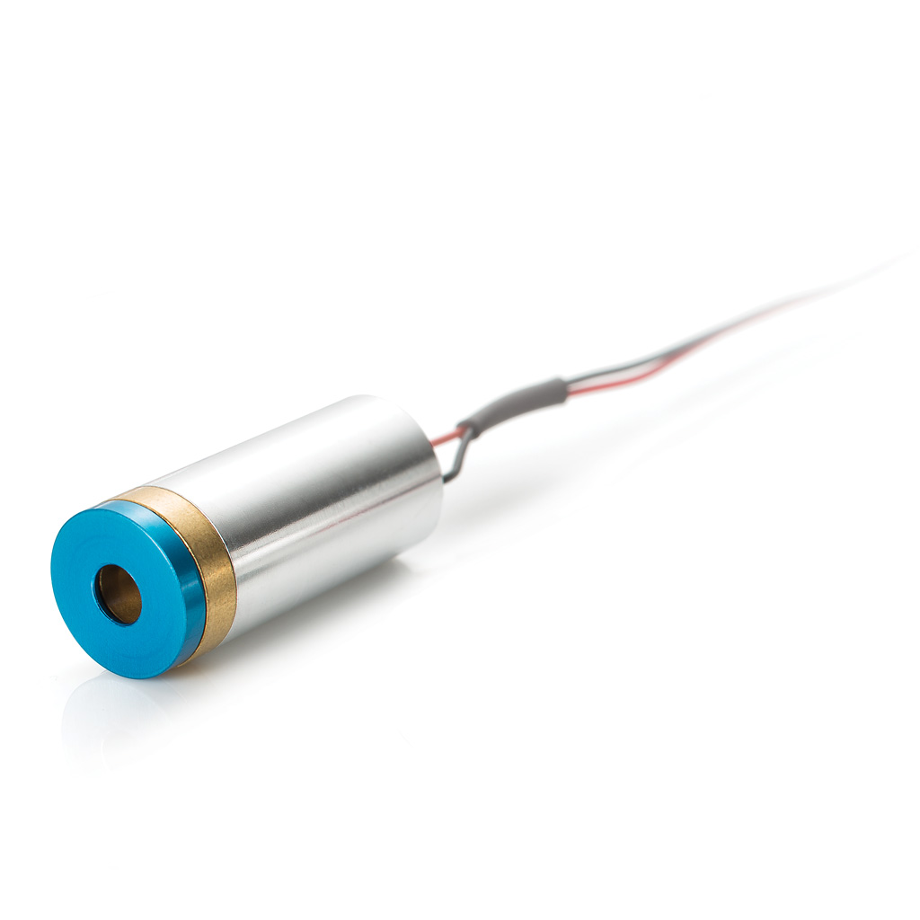
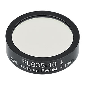
Since the Raman phenomenon only occurs with approximately every one in ten million photons, we want to make this response as distinct and as strong as possible. To do this, we need use a concentrated source of light: a laser. The laser by Coherent shown on the top right is similar to that of ours, which has a 635nm wavelength at 5mW. To calculate the Raman shift requires us to know the wavelength of the incident light. Since many sources of light, including lasers are not perfectly monochromatic (having only one wavelength), we need to filter out all the light of different wavelengths. This can be done using a laser line filter shown in the bottom right, which only lets past it light of 635nm.
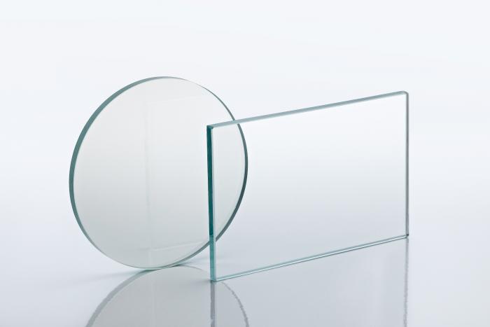
To avoid having to align too many focal points, we use a beamsplitter, shown on the left, which allows us to get the light collimated as it comes back through the objective lens. By using a beamsplitter, we are accepting a loss of laser and raman light. Our beamsplitter in particular has a 70% reflectance rate and 30% transmittance rate. What this means is 70% of the laser light is reflected through the objective lens onto the sample and on the way back, 30% of the light from the sample, including the raman light, is transmitted through the beamsplitter.
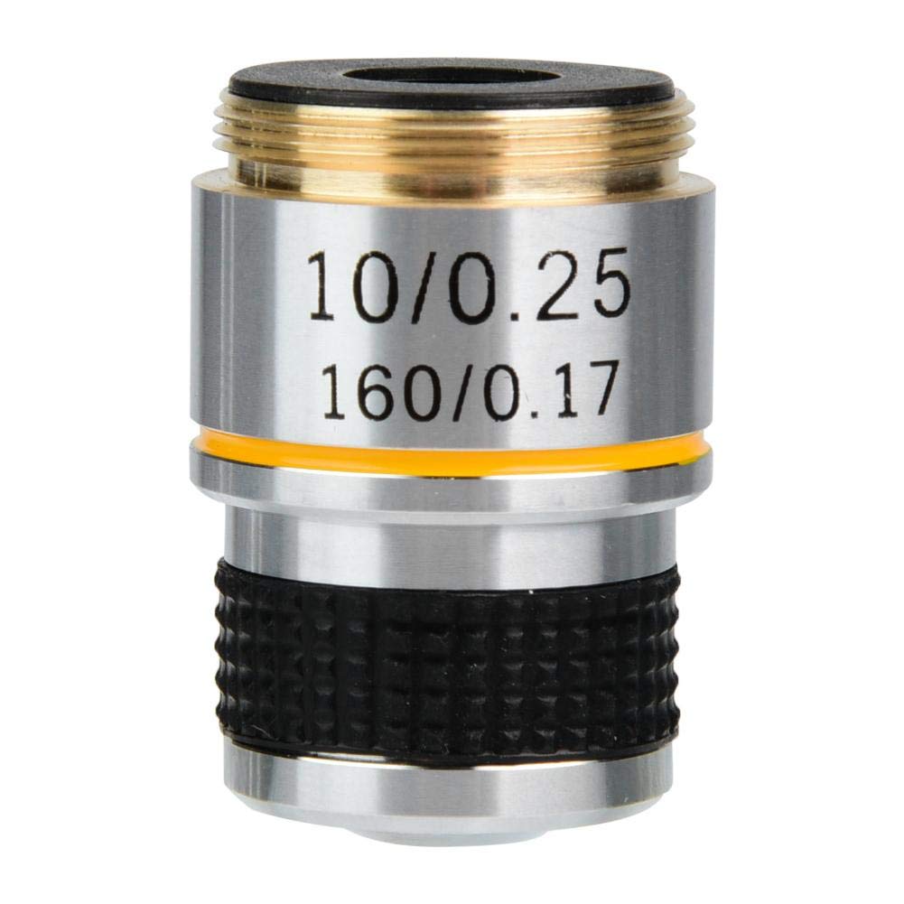
To get a stronger Raman signal, we want to increase the intensity of the light that we have hitting the sample. One way to do this is to focus the light, using a microscope objective lens as shown on the right. When you go "forwards" through the lens, the light is focused at the objective lens's working distance, which is 7.1mm in our case. To be able to take advantage of the properties of a diffraction grating, we need all the light to hit it at approximately the same angle. To force all the light to be as parallel as possible, we can put the light through the objective lens backwards which collimates the light. This means that all the light coming out of the objective lens is parallel and therefore would hit the diffraction grating at the same angle.
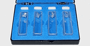
To store the sample to be tested, we use a quartz cuvette. The reason we use quartz is because of its unique light transmittance properties; it transmits approximately 90% of all light from 280-2500nm. This makes it ideal as it is versatile and allows us to work with lasers of different wavelengths, but more importantly, it will not hinder the transmission of the raman signal from the sample.
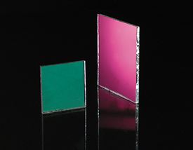
Since lasers are just focused beams of light, they are very intense on the points they hit. Raman signals are often very weak as we lose alot of the light just from the fact that it's dispersion is 360˚, and not to mention that they also occur one in ten million photons. To minimize the amount of other light (noise) hitting the CCD, we want to filter out the strongest source of light: laser light. We do this by using a notch filter pictured on the left. Notch filters are pieces of glass that have a very special property of light transmittance. These pieces of glass are designed to transmit all light except that of a single wavelength. However, it is impossible to truely block out all of the light of a particular wavelength, and so the transmittance is represented by ODx, where 10^-x is the percentage of light of that light that gets through the filter. In our case, we have a 633nm OD3 notch filter which means that 0.1% of of 633nm light is able to get through the notch filter.
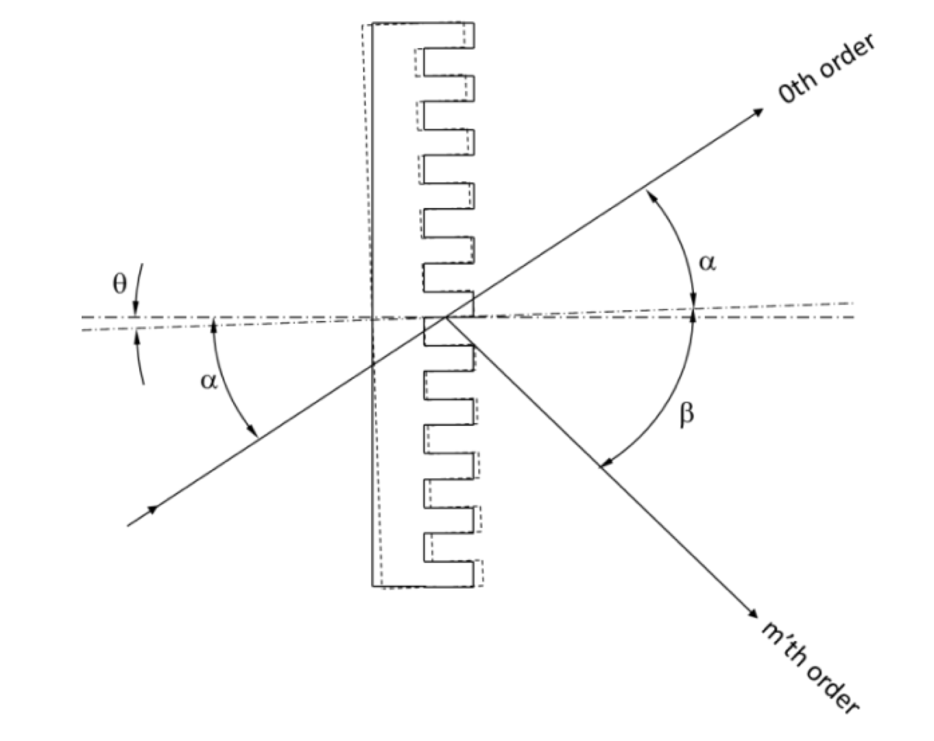
Since we have many wavelengths of light coming back from our sample (since there is a whole raman spectrum), we need to be able to separate the light by wavelength. We can do this using a diffraction grating. Diffraction gratings work by having multiple parallel slits, and when light goes through these slits, they are diffracted at angles determined by their wavelength. To calculate the angle of diffraction, we can use the equation:
a[sin(α) + sin(β
)] = mλ
where a is the distance between the slits, α is the angle of incidence, β is the angle of diffraction, m is the order of diffraction, and λ is the wavelength of the light. In our case, we have a grating with 1000 lines per mm, incident angle of 0˚, first order diffraction, and incident wavelength of 680nm. The diffraction angle we get from this caculation is 42.8˚.
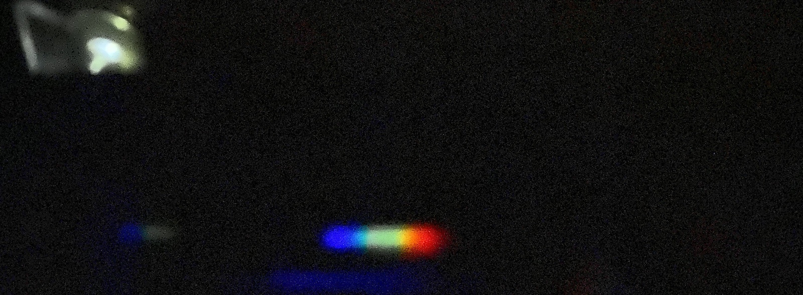
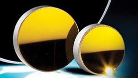
Since we have such a weak signal, we need to collect as much of the light coming off the diffraction grating as possible and focus it onto the CCD. This can be done in two different ways. In the first method, we would collect the light and focus it using a focusing lens onto a planar mirror, which would reflect the light back to the CCD. We chose the second method which is where we used a concave focusing mirror to collect the light and focus it onto the CCD. Using this type of mirror increases the challenge of allignment but only involves a single component. On the right, we can see our light on the CCD as a relatively narrow strip which is exactly what we want. Shown above it are the concaved focusing mirrors we have.
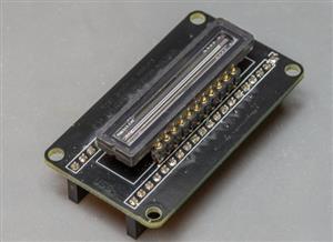
To sense light, we need a device that is able to detect photons. For most spectroscopy applications, charged coupled devices (CCD) are used for their super high sensitivity to light which is what we need for inherently weak signals such as Raman. Our CCD, the TCD1304 shown on the left, has a linear array of 3648 pixels that create voltage when hit by photons. This CCD in particular has been used in many spectroscopy solutions, including those from Ocean Optics. In order to drive this CCD, we need to provide it with three signals: clock, shutter (sh), and integration clear gate (ICG). To better understand the