|
University of Massachusetts Amherst
Adaptive Use Bridge Project |
|
|
< Return to Call Road Bridge
Call Road Bridge Tension Test Methods Download a summary table of these tension test results Tension coupons were fashioned from four different structural members from the Call Road Bridge. Eight coupons were created from two beam hangers, four coupons were created from an eye-bar, originally part of the bottom chord of the bridge, five coupons were created from a loop-bar, a tension diagonal, and four coupons were machined from lacing cut from a portal frame that provided lateral bracing to the bridge. 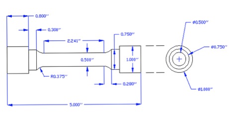 Figure 1. Bondsville beam hangers before being cut into tension coupons. The coupons were held in the tension machine by custom made shoulder grips. Figure 2 features a photograph of the tension grips. 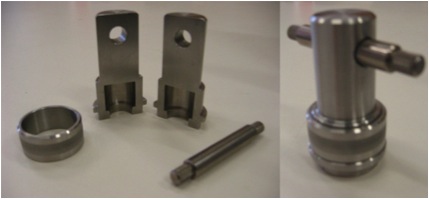
Figure 2. Custom made shoulder grips used to hold the tension coupons during testing.
The wrought iron obtained from the lacing members was machined into plate type specimens with 0.2 inch thickness and 0.5 inch width gage section; dimensions of this coupon type can be seen in Figure 3. The specimens were held in the machine with wedge grips, which held on to either end of the coupon. 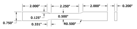 Figure 3. Custom made shoulder grips used to hold the tension coupons during testing. Material from the eye-bar was machined into plate type specimens with a 0.65 inch thickness and 1.5 inch width in the gage section; dimensions of this coupon type can be seen in Figure 4. The specimens were held in the machine with wedge grips, which held on to either end of the coupon. 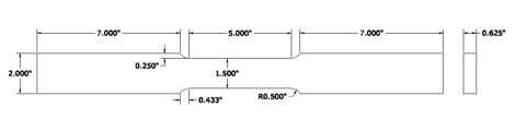 Figure 4. Plate type tension coupon used for material from the eye-bar. Material from the looped-bar was machined into plate type specimens with a 0.65 inch thickness and a 0.8 inch gage section width; dimensions of this coupon can be seen in Figure 5. The specimens were held in the machine with wedge grips, which held on to either end of the coupon. 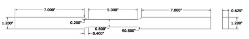 Figure 5. Plate type tension coupon used for material from the eye-bar. Testing for the round coupons and plate coupons machined from lacing members was conducted in an Instron testing machine. Initially a load rate to 0.005 inches of strain per minute until 20 ksi of stress was reached. During this time, an extensometer was used to accurately measure strain. After 20 ksi of stress was reached, the extensometer was removed and the strain rate was increased to 0.05 inches per minute. The testing machine's cross head displacements were used to record strain measurements after the extensometer was removed. Testing continued until the specimen failed. In order to test the larger plate coupons from the eye-bar and looped-bar, a 500 kip Tinius Olsen testing machine was used. A load rate of 0.1 inches of strain per minute was used throughout the entire duration of the test. After a stress of 20 ksi was reached the extensometer was removed and the testing machine's cross head displacements were used to record strain measurements. Testing continued until the specimen failed.The extensometer is an accurate yet fragile measurement tool. To avoid damaging this piece of equipment it was removed while each test was still in progress. It was found that the cross head displacement measurements made by the testing machine were precise however inaccurate. A method to correct the results and remove this inaccuracy was developed and applied to all of the raw data. The stress-strain elastic range's linear behavior was used to correct misleading data. Figure 6 includes uncorrected and corrected stress strain plots for a tension sample. 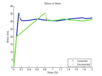
Figure 6. Uncorrected and corrected stress strain diagrams. The tension test results provide valuable information on the material at hand. The modulus of elasticity, yield strength, tensile strength and percent elongation at failure can all be obtained from tension testing. These material properties are used when planning reconstruction of historic bridges. |

|
This material is based upon work supported by the National Science Foundation under
Grant No. DUE-0736972 and Award 0552548.
Any opinions, findings, and conclusions or recommendations expressed in this material are those of the author(s) and do not necessarily reflect the views of the National Science Foundation. |