Images
< Return to Images menu
Southern Vermont (1906) Bridge
More information on the Southern Vermont (1906) Bridge
|
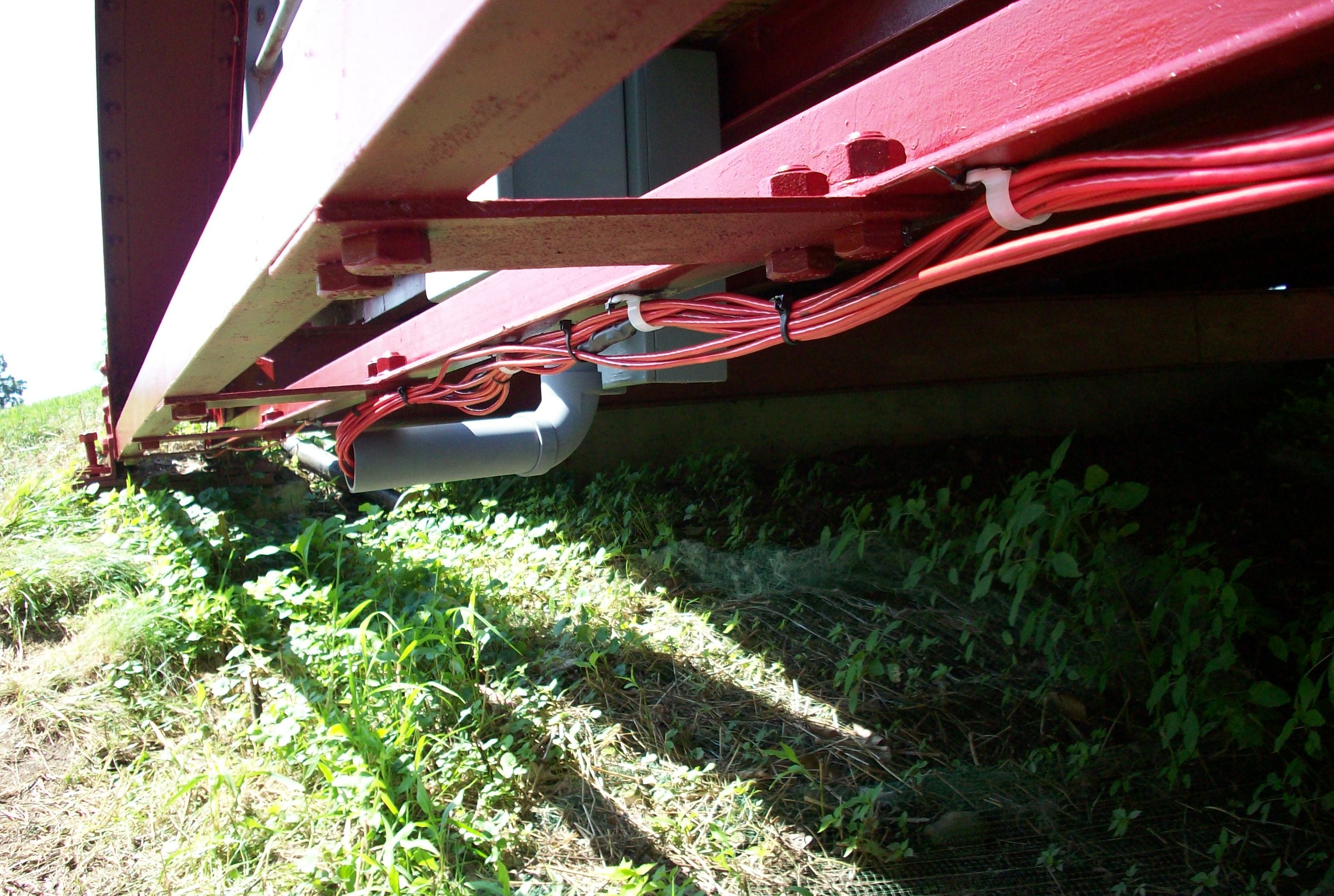
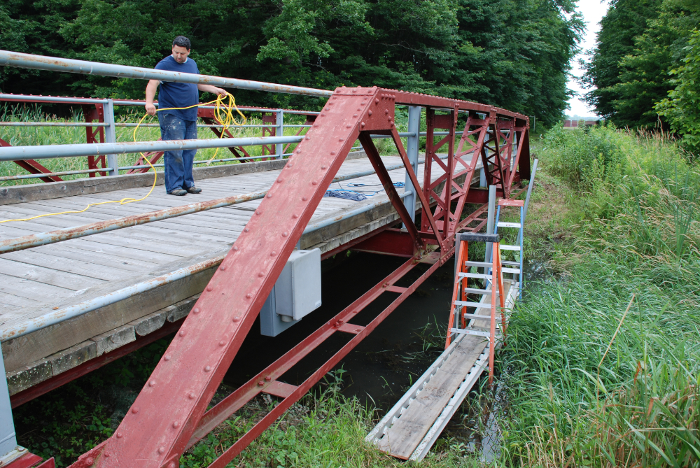
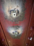
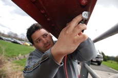
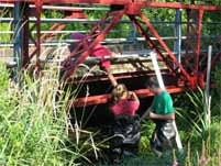
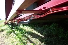 The wire leads into the PVC pipe and up into the terminal box.
 |
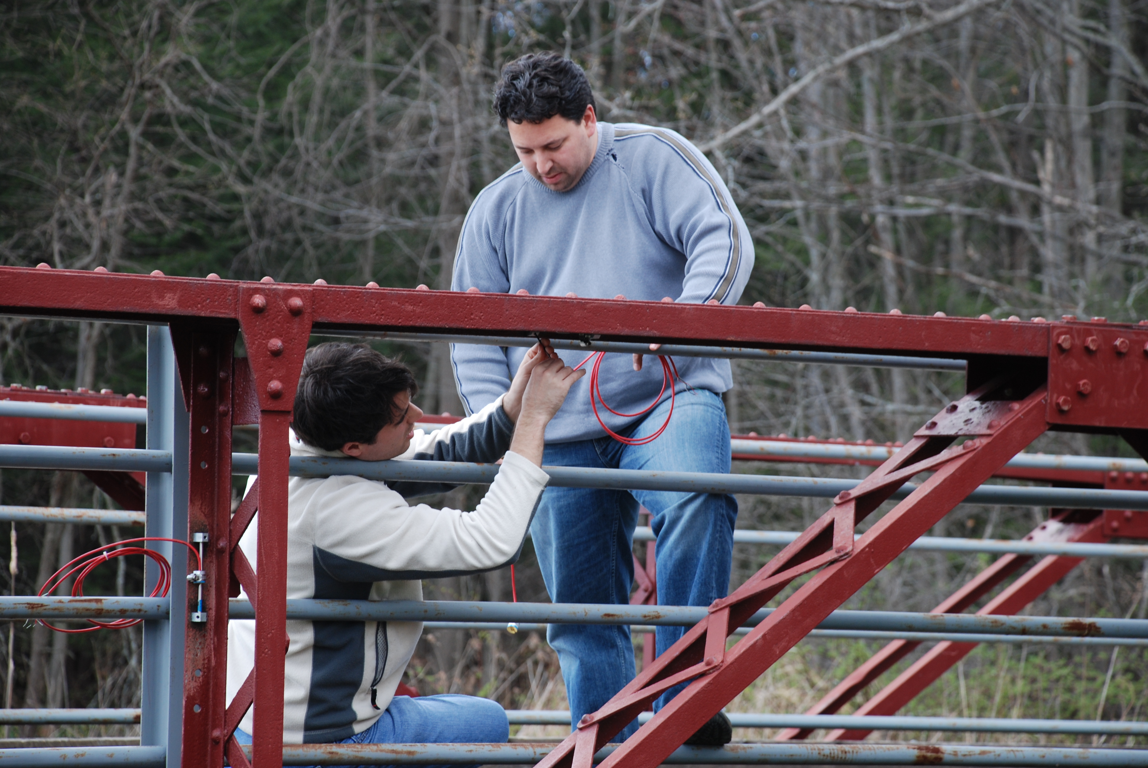
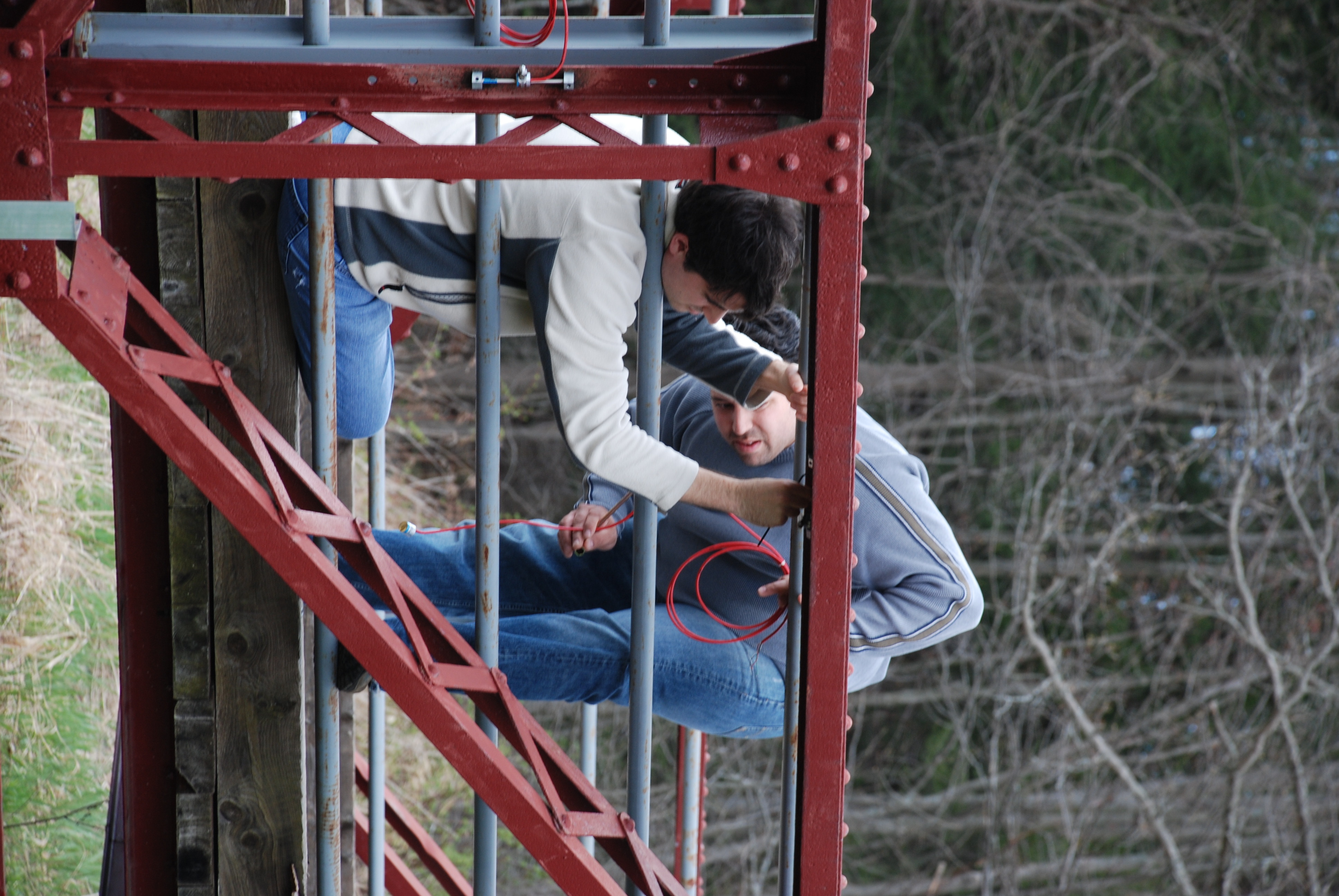
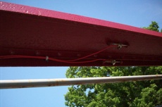 Strain gages have been installed in the blocks and the wire is run to the terminal box.
 |
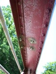
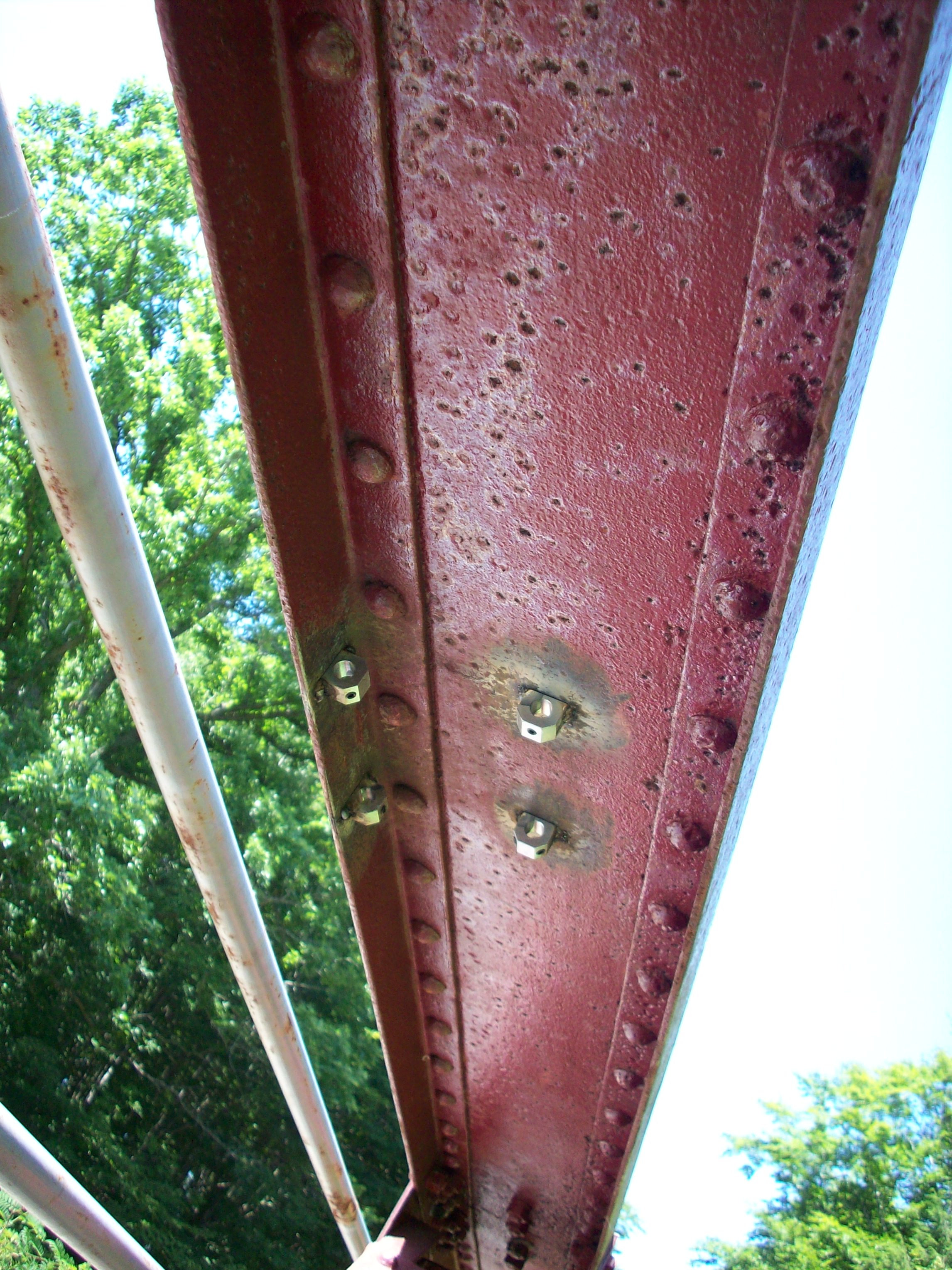
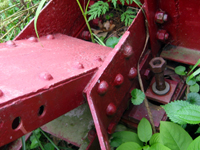
Blocks that have been welded onto the plate and deckside angle of the top chord.
|
|
|
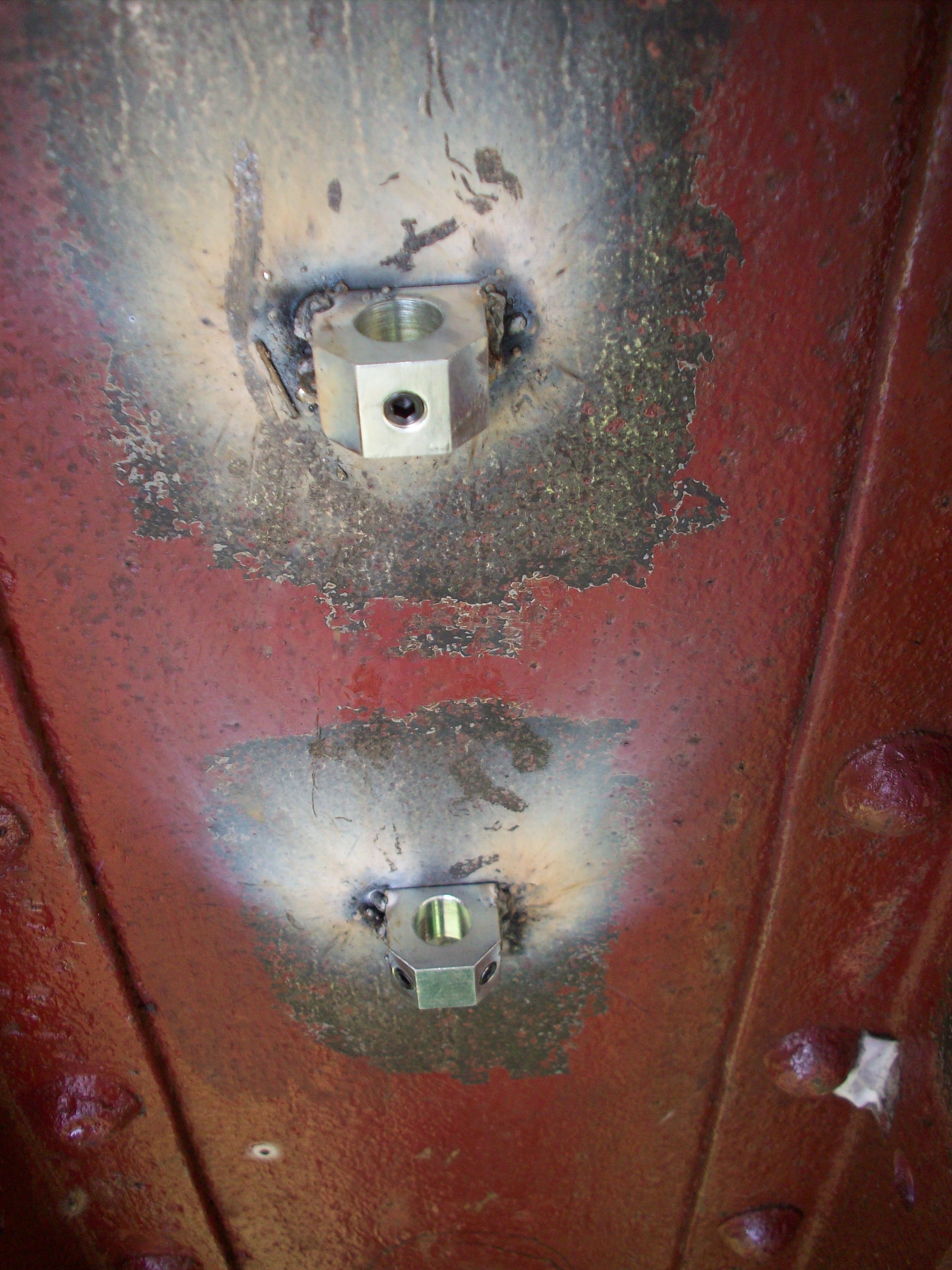
Two blocks that have been welded onto the top plate.
|

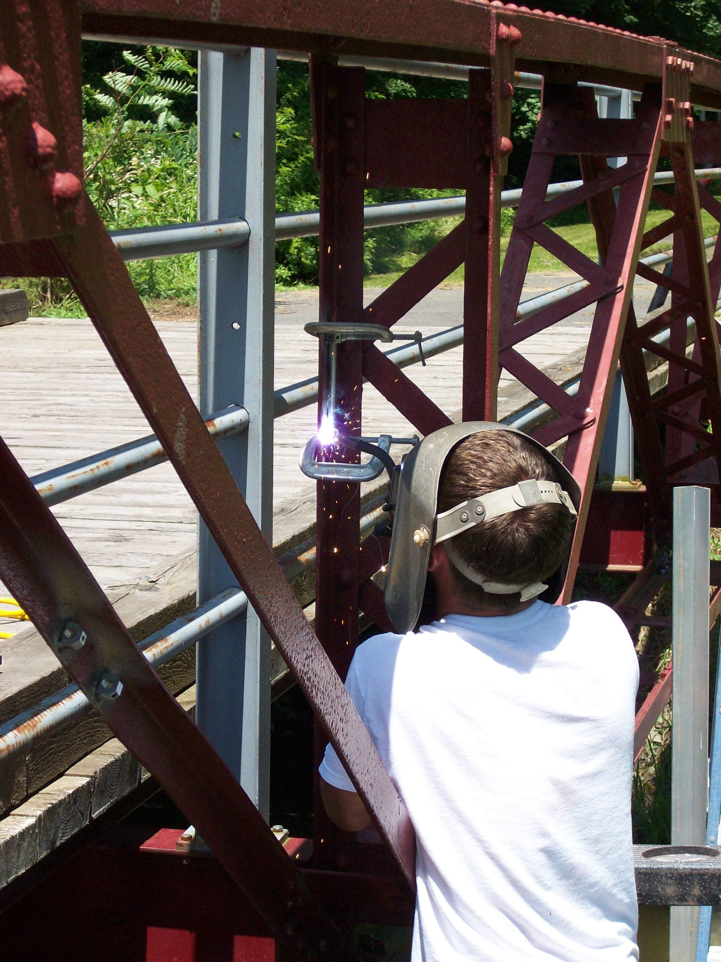
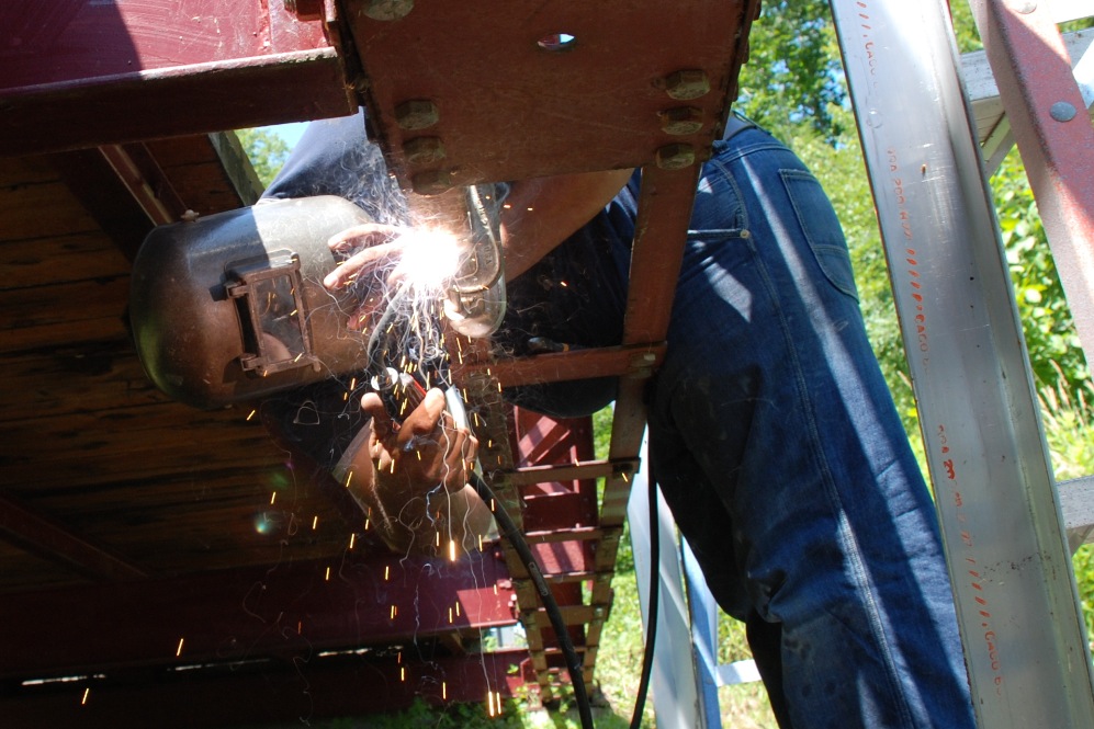
Johnny welds a block onto the vertical member. |
 Randy welds one of the blocks onto the deckside angle of the bottom chord.
 |
|
|
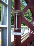
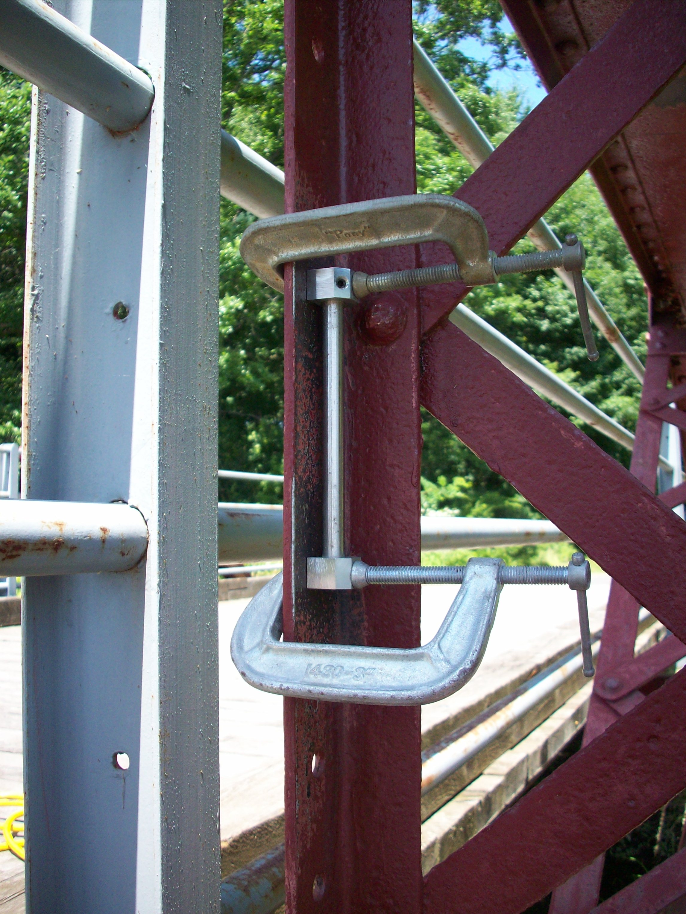
The blocks were held using clamps so that they could be welded.
|
 Johnny grinds the paint off the bridge so the blocks that hold the gages can be welded. Johnny grinds the paint off the bridge so the blocks that hold the gages can be welded. |
 Johnny grinds another gage location. Johnny grinds another gage location. |
|
|
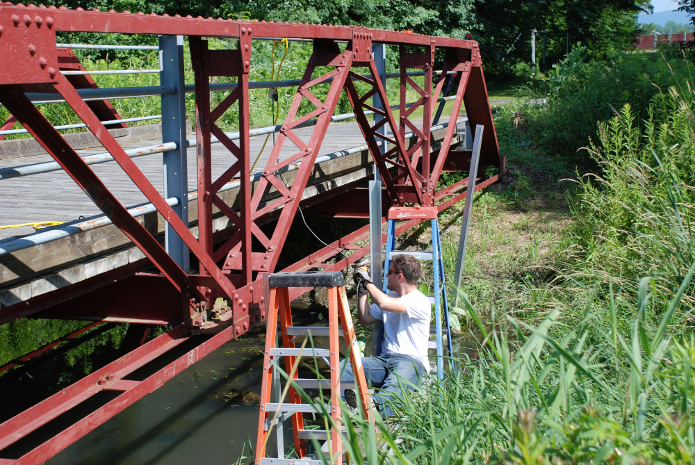
 Randy on the bridge in July 2009 while getting it ready to weld. Randy on the bridge in July 2009 while getting it ready to weld. |
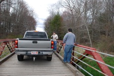 Prof. Lutenegger used his truck for a test to make sure the gages would take readings. Prof. Lutenegger used his truck for a test to make sure the gages would take readings. |
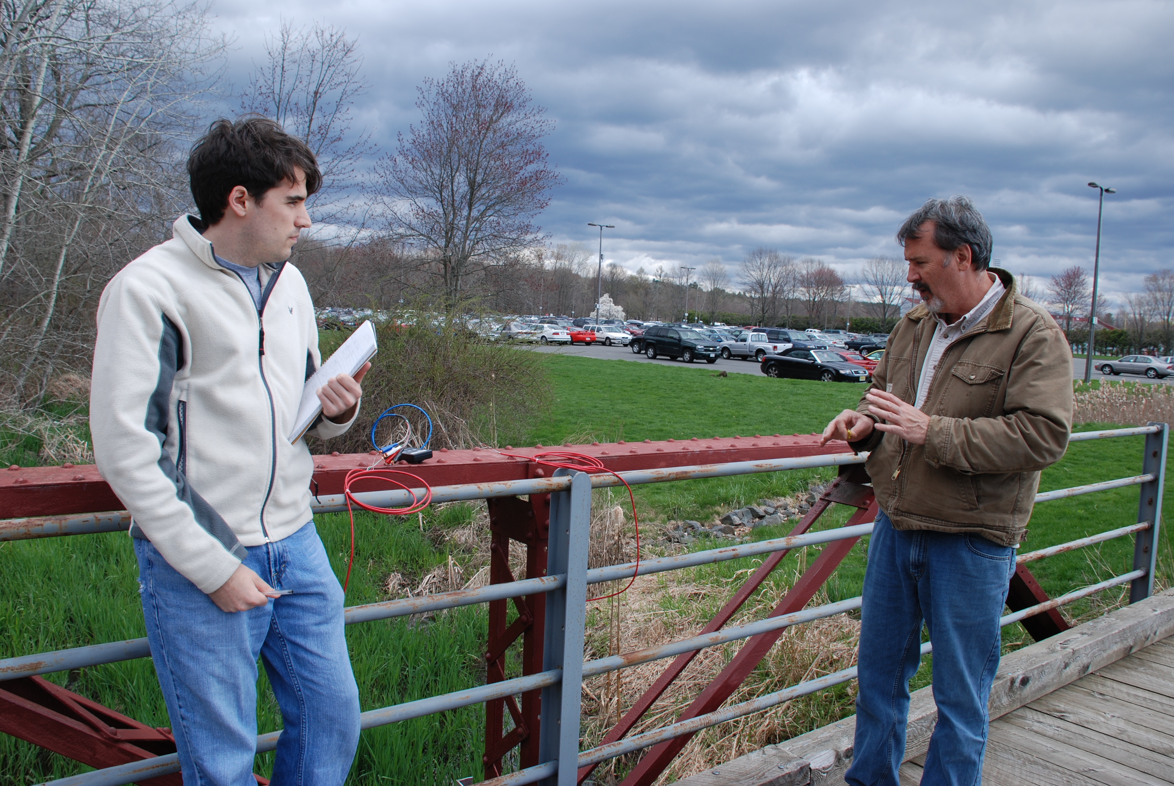
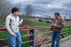 Prof. Lutenegger discusses the gage placement with Sean. Prof. Lutenegger discusses the gage placement with Sean.
|
|
|
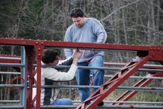 Sean and Randy.
 |
|
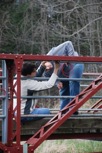
 Randy checks a gage location.
 |
|
|
|

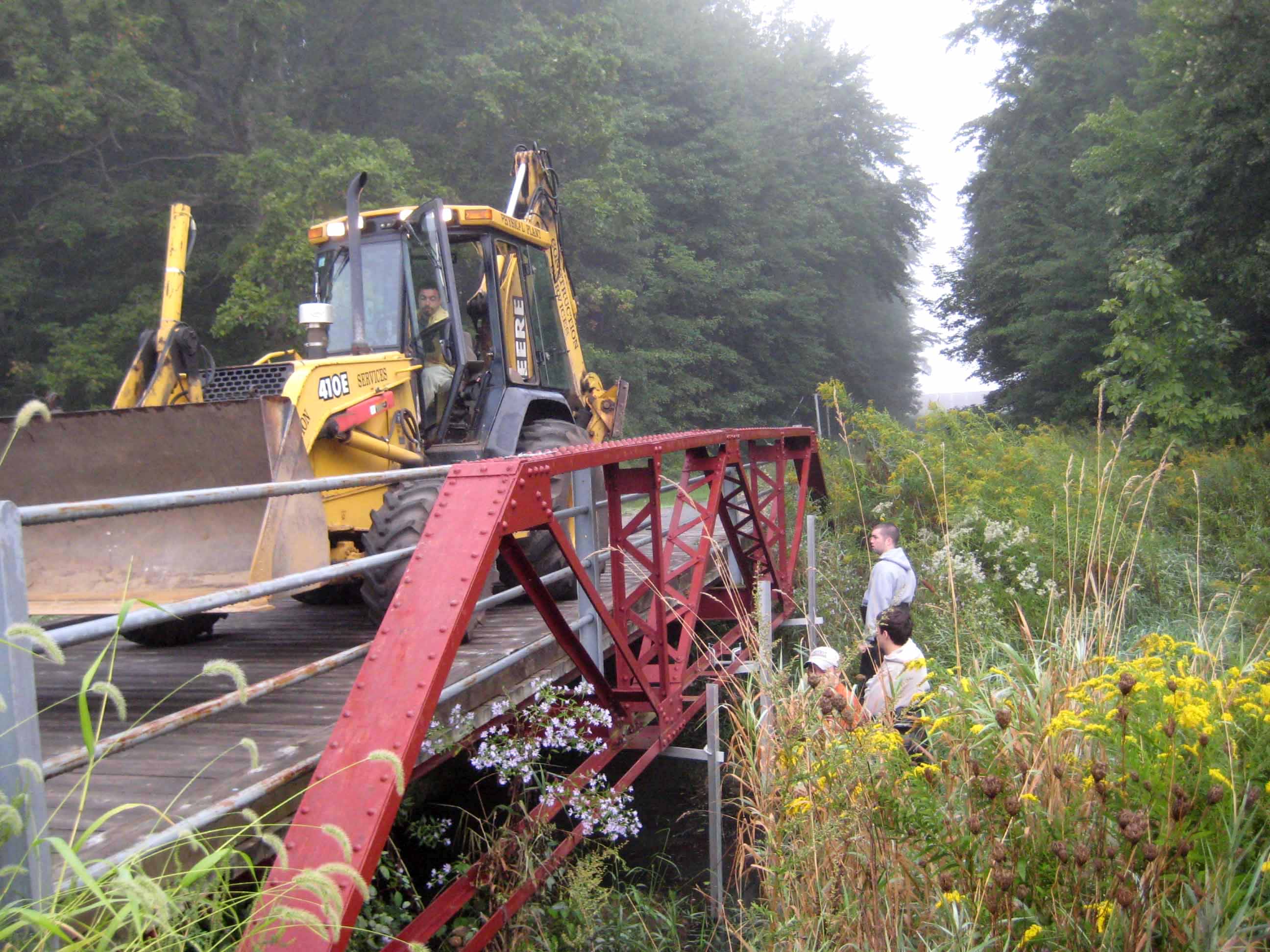
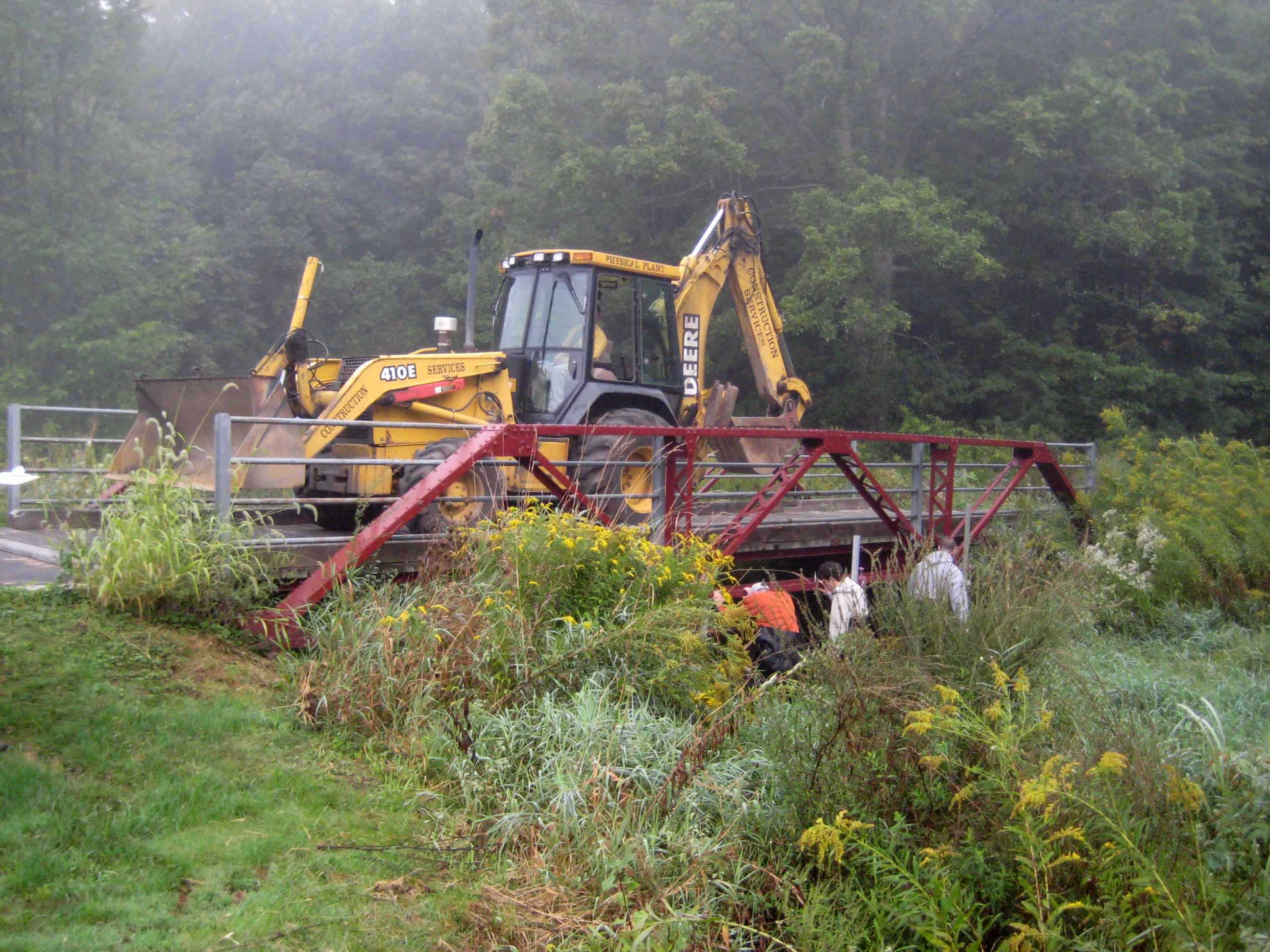
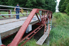
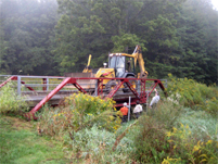
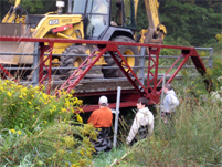
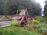
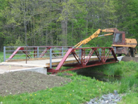
The Southern Vermont (1906) Bridge during load test 2. |

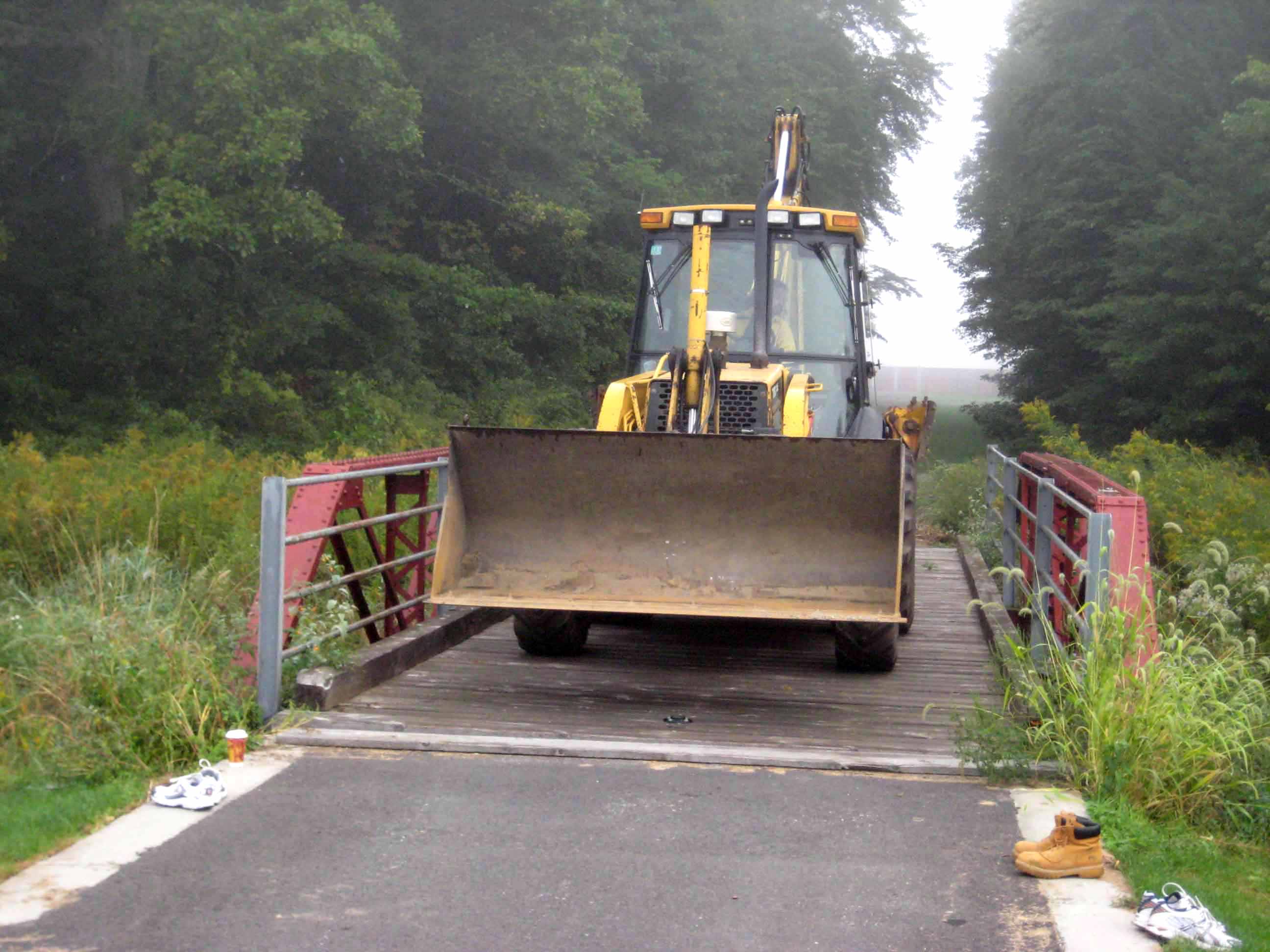
The loader was moved to 3 different locations during load test 2.
|
|
|
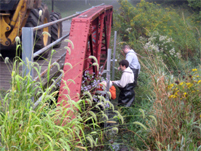
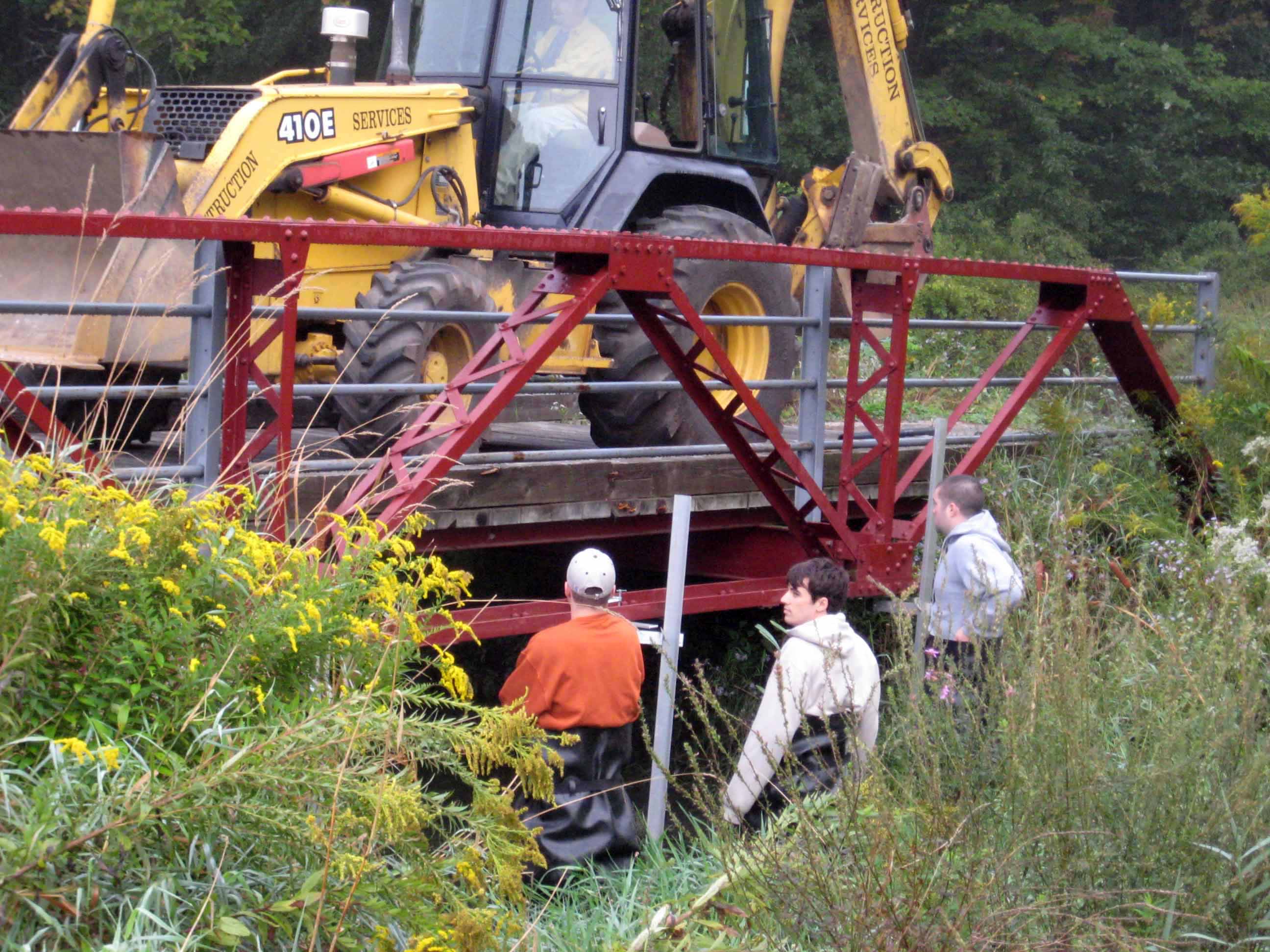
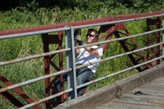
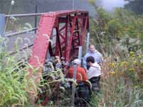
Ryan Mones ducks under the bridge to take a deflection measurement during load test 2. |
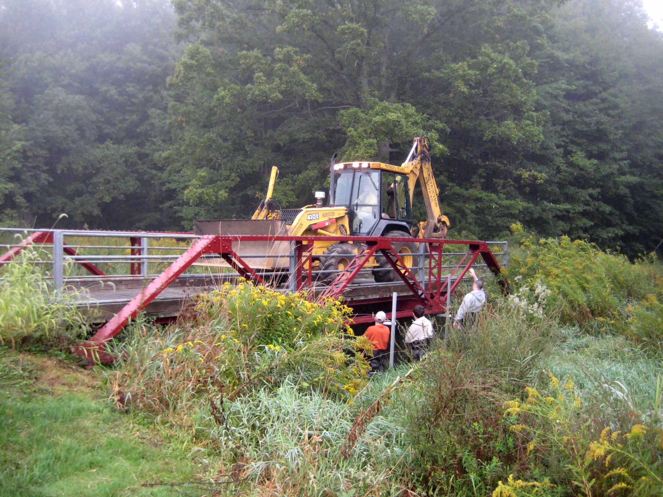
Patrick Veale helps position the loader on the bridge during load test 2. |
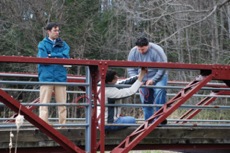
Ryan, Sean and Patrick assisting with load test 2. |
|
|
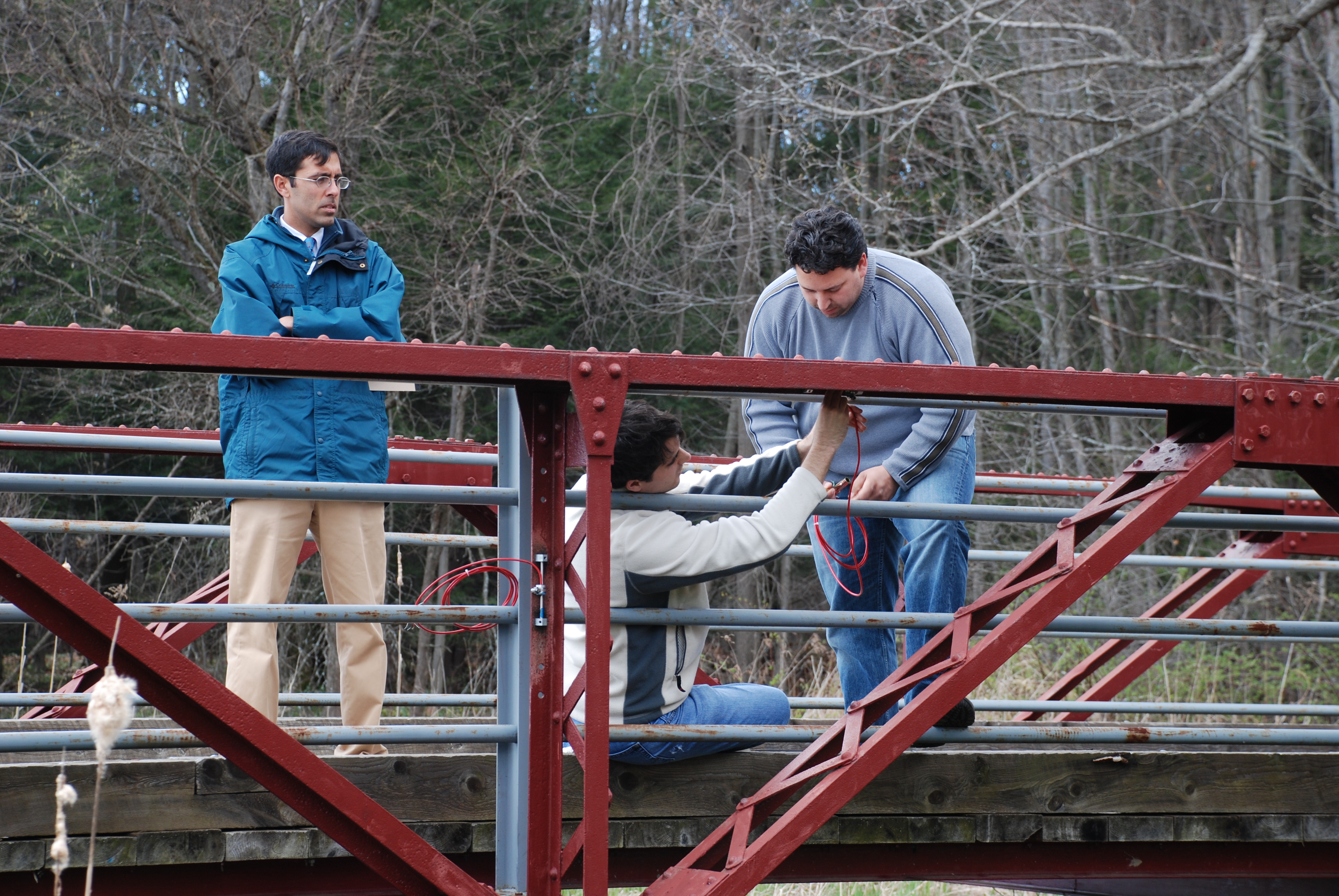
Professor Arwade helping coordinate load test 2. |
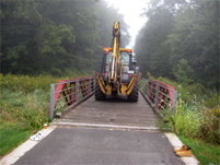
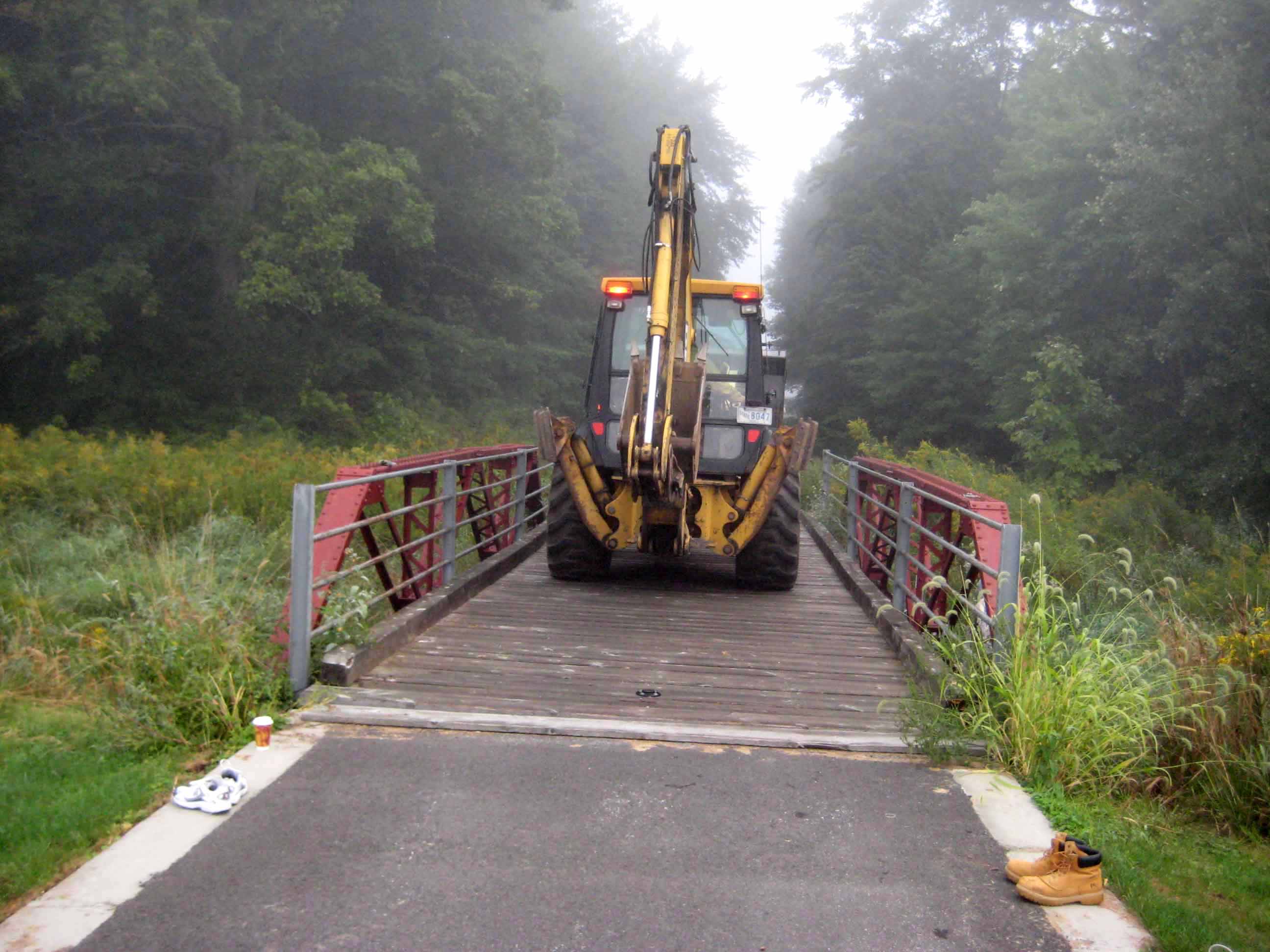
The loader in forwards orientation (operator facing north). |
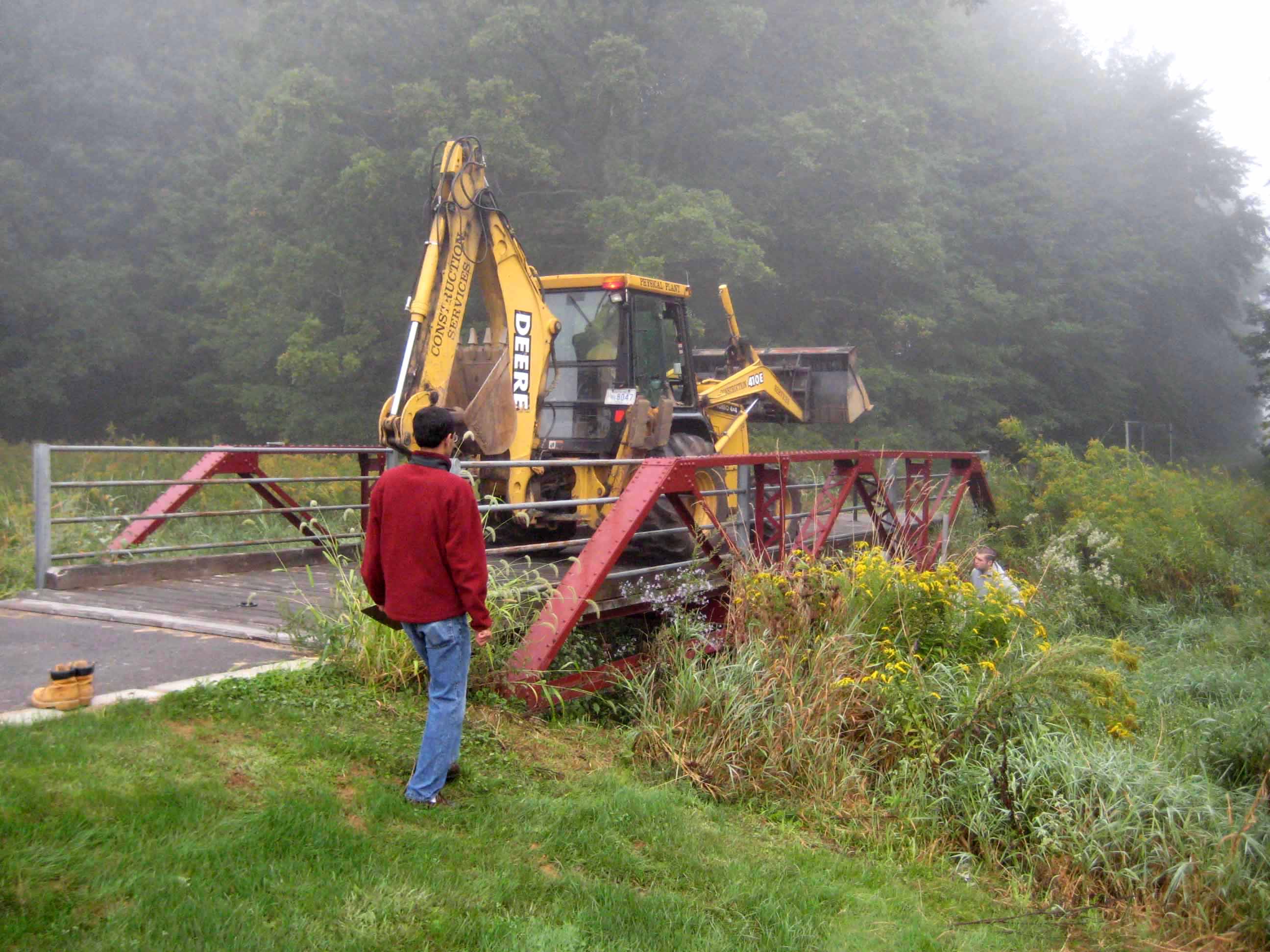
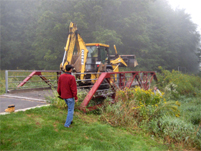
The equipment operator and civil engineering students worked together to get the loader into the perfect position during load test 2. |
|
|
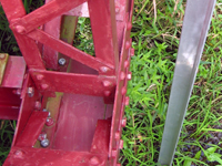
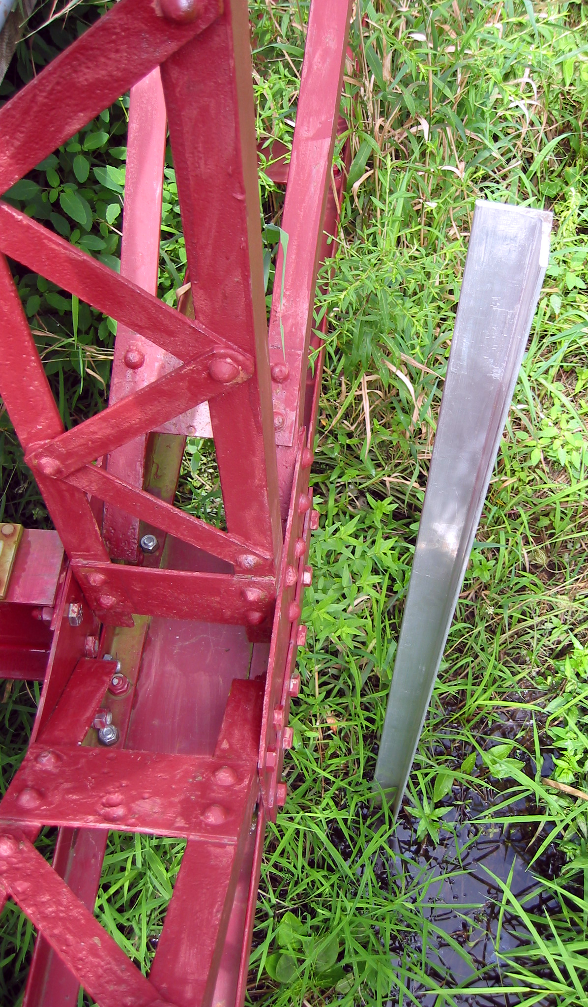
Angle driven into the ground to hold electronic dial gage for load testing. |
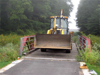
Placing the loader for load test 2. Loader shown in backwards orientation (operator facing south). |
Civil Engineering students enjoying an early morning load test. |
|
|
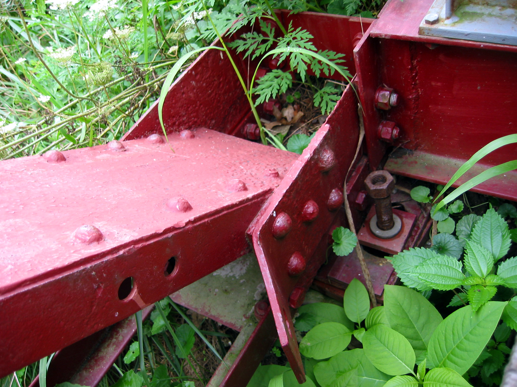
Southern Vermont (1906) Bridge Support. |

Placing angle members into the ground during load test 1. |
The location of the angle members is discussed during load test 1 |
|
|
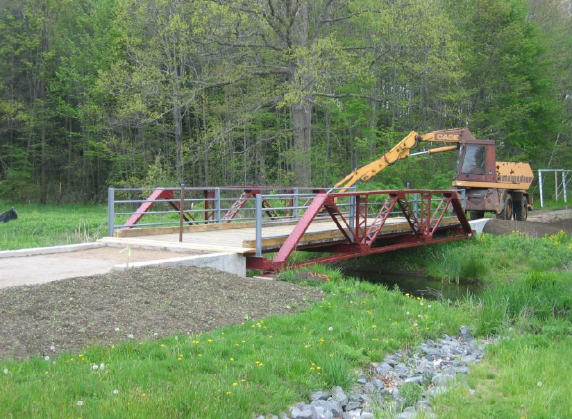
The Southern Vermont (1906) Bridge after being reconstructed on campus. |
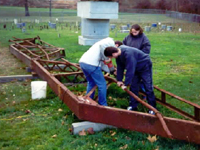
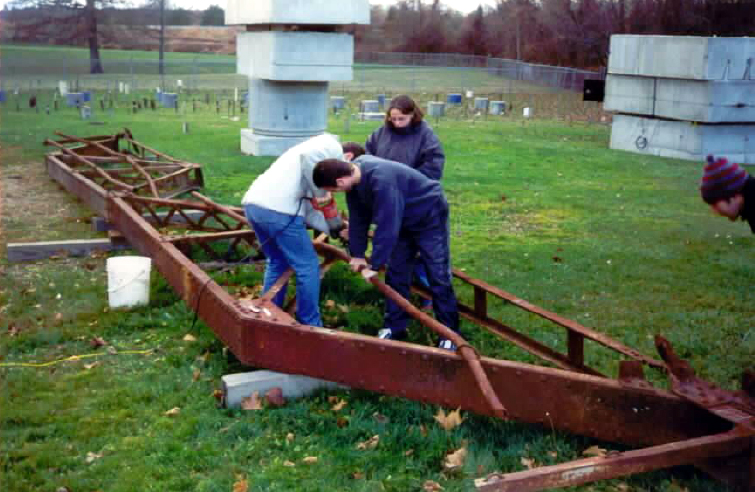
Students remove the original handrail from the bridge. |
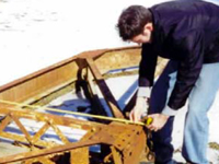
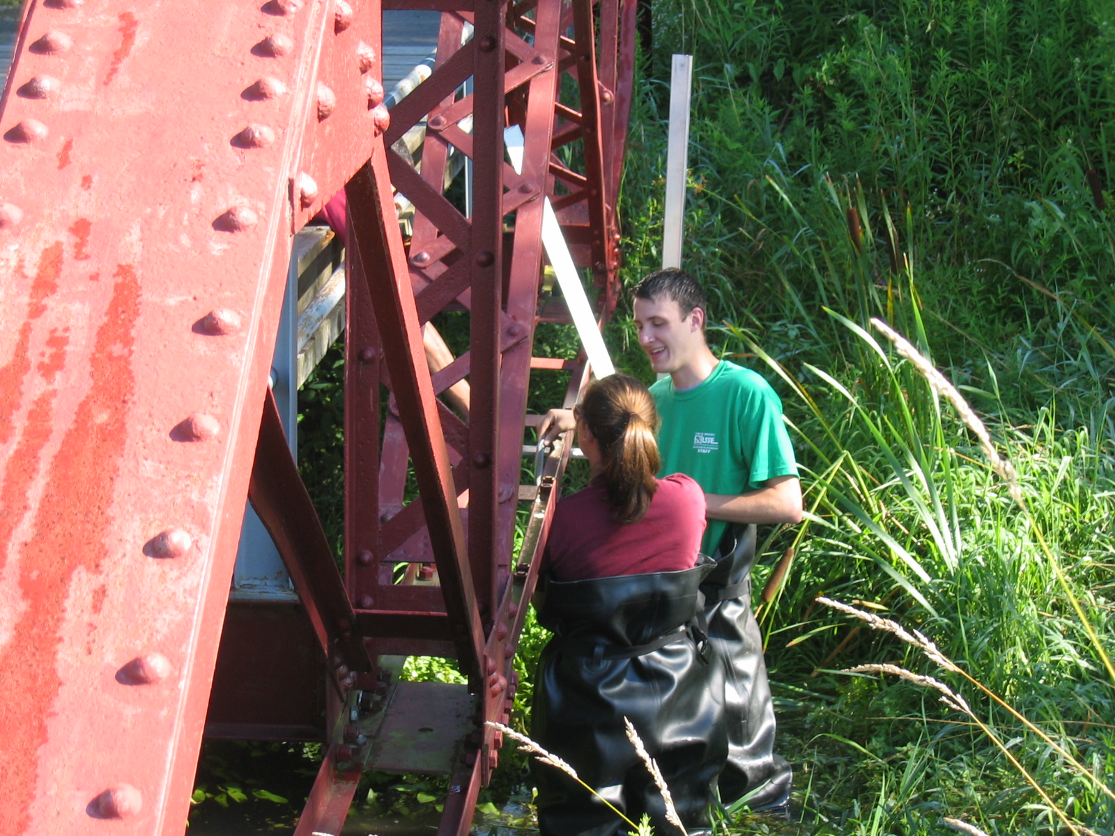
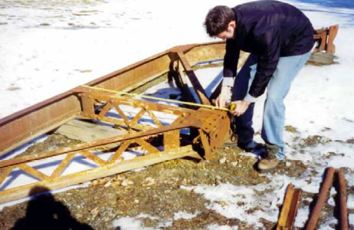
A student measuring the bridge's truss during the winter time. |
|
|