|
University of Massachusetts Amherst
Adaptive Use Bridge Project |
|
|
< Return to Southern Vermont (1906) Bridge
Southern Vermont (1906) Bridge Load Test 1 Methods View the results for this load test here Displacement measurements for this load test were taken with electronic dial gages. The dial gages were supported by seven foot angle members that were driven approximately 1.5 feet into the soil beneath the bridge. These angle members were stable in the ground and did not move any significant amount during data collection. Figure 1 features a sketch of the dial gage installation. Figure 2 features a photograph of the bridge during the installation of dial gages. 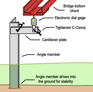
Figure 1. Electronic dial gages were attached to angle members driven into the soil. 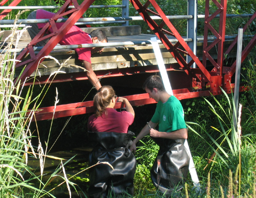
Figure 2. Members of the Adaptive Use Bridge Project team installing electronic dial gages on the Southern Vermont (1906) Bridge. The dial gages were installed at three different locations along the bottom chord. The locations of the gages can be seen in Figure 3. The gages were not moved during data collection. 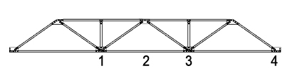
Figure 3. The dial gages were located at points 1, 2 and 3 along the bottom chord of the bridge. After the three dial gages were properly installed all people and objects were removed from the bridge and the gages set to zero. The bridge was then loaded with a Chevy Silverado 1500 Extended Cab truck. The truck used has a wheel base of 12 feet and a curb weight of 5266 lbs. Displacement measurements were taken with the truck's front axle above locations 1, 2 and 4 in Figure 3. While the gages were being read the truck remained stationary on the deck of the bridge. |

|
This material is based upon work supported by the National Science Foundation under
Grant No. DUE-0736972 and Award 0552548.
Any opinions, findings, and conclusions or recommendations expressed in this material are those of the author(s) and do not necessarily reflect the views of the National Science Foundation. |