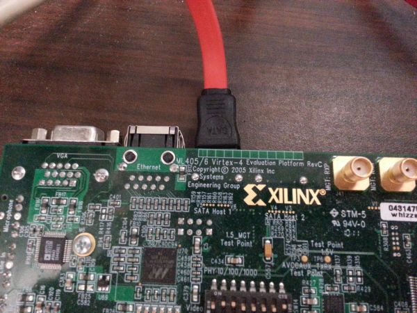
An Open Source SATA Core for Virtex-4 FPGAs
All layers of the SATA protocol are implemented in this SATA core. The design utilizes the RocketIO Multi-Gigabit Transceivers of the Virtex-4 for physical layer functionality.
This design is based on a SATA core created at the University of North Carolina at Charlotte for Virtex-6 devices, created by Ron Sass, Ashwin Mendon, and Bin Huang. That design is available here. Some new features have been added in this version, including a replay buffer to improve reliability and new debugging modules.
Download
Files for the SATA core are available here.
Organization
The main modules in the SATA core are organized like so:
-sata_core.v
   -command_layer.vhd
   -link_layer.vhd
      -scrambler.vhd
      -crc.vhd
   -sata_phy.v
      -rocketio.v
      -oob_sequence_controller.v
         -oob_sig_gen.v
         -comwake_detector.v
         -cominit_detector.v
Using the Core
The design includes a Xilinx ISE project file for use on the ML405 evaluation board. This project instantiates the SATA core and demonstrates functionality with a simple test. Connect a hard disk or SSD to the SATA Host 1 connector (left side when viewing the board from above).

A simple counter pattern is written to the disk when the user presses the GPIO_SW_S button. To reset the core, use GPIO_SW_W. LED3 indicates that the SATA link is up. You can connect the disk to a PC and use a hex editor to verify that the data was written.
The core uses a simple FIFO-like interface and supports Read or Write commands. Use the cmd_type port to select the operation, and the new_cmd port to begin. Be sure to check the ready_for_cmd and the LINKUP signal before starting an operation. See sata_core.v for more information.
On Other Boards
The SATA core requires a 150MHz reference clock to operate at SATA I speeds, and a 300MHz reference clock to operate at SATA II speeds. These clocks need to be low-jitter, in accordance with the guidelines in Chapter 2 of the RocketIO User Guide. Also needed is an independent system clock for the SATA initialization sequence.
Timing parameters
Some parameters are based on the speed of the system clock. The default values for these parameters are for a 100MHz system clock, as on the ML405. If your clock is a different speed, they will need to be changed to match your system clock speed.
In the file oob_sequence_controller.v, the oob_sig_gen, cominit_detector, and comwake_detector modules are instantiated with such timing parameters. Change these to the nearest integer value that corresponds to the parameter time. For example, if you were to use a 60MHz clock, the COUNT_106NS parameter should be set like so: 106e-9 * 60e6 = 6.36 -> Round to 6.
If you plan to use the event logger for debugging, then the UART's clock divide parameter must be changed. See the header of this file for instructions.
The RocketIO's DRP clock is created in sata_phy.v by dividing the system clock rate in half. However, this clock must be under 50MHz. If your system clock runs at greater than 100MHz, be sure to edit this to divide the clock further or supply a separate clock. Also, be sure to set the correct value for the DRP clock in the RocketIO Wizard. For example, if using a 60MHz clock, set the DRP clock to 30MHz in the RocketIO Wizard.
Using the RocketIO Wizard
The SATA Physical layer uses the Virtex-4 RocketIO transceivers. The parameters for the RocketIO are set using the RocketIO Wizard. These include the placement of the MGTs and the line rate. To change these settings, click the rocketio.xco file in ISE to launch the Wizard.
Note: MGTs must be instantiated in pairs. See the User Guide.
Select either the SATA I or the SATA II protocol file, depending on your available reference clock and disk. Note that the SATA core does not implement speed negotiation, so a SATA I disk will not work with the core if SATA II is used. Select your MGTs and reference clock. Be sure to set "Data Width" to 32 bits for both the transmitter and receiver. Set your reference clock speed and the appropriate line rate (1.5Gbps for SATA I, 3.0Gbps for SATA II). Be sure 8b/10b encoding is enabled (it should be by default).
The remainder of the settings can be left at their defaults, except for the DCLK Rate. This is the DRP clock speed and should be set according to your system clock, as described above.
The Wizard generates wrapper files, constraints files, and an example design. Some of these files are already referenced in the project, so they will update automatically. However, there are some changes that need to be made after running the Wizard.
mgt_attributes.ucf references the rocketio_i instance, but this is not at the top-level in the design. This can be easily fixed with a Find & Replace operation. Replace "rocketio_i/" with "sata_core_i/sata_phy_i/rocketio_i/", or the appropriate place in your design.
Parameters in the sata_core.ucf file may also need to be changed. Look at example_mgt_top.ucf, generated by the Wizard, to see what these values should be.
Setting the OOB threshold
The values created by the Wizard are correct, except for the value of RXCDRLOS. This parameter controls the OOB detection threshold. As described in XAPP716, there is a problem with the OOB detector where this parameter does not function accurately. Each MGT and each Virtex-4 may require a different value for RXCDRLOS.
The correct value can be found using Chipscope. Using the Physical Layer ILA, watch the rxsigdet signal while your hard drive is connected and powered on. Until the OOB sequence is complete, rxsigdet should be high except for when the disk sends OOB signals. If rxsigdet is always low, then your RXCDRLOS value is too low. If rxsigdet is always high (use a trigger to watch for this), then your RXCDRLOS value is too high. Correct operation is shown below.

License
The SATA core is released as open-source under the GNU General Public License.
Contact
This page is maintained by the Reconfigurable Computing Group at University of Massachusetts Amherst .
Back to top