Hardware Diagram
Matthew Avison - Carley Davis - Ivan Norman - Cory Vandergrift

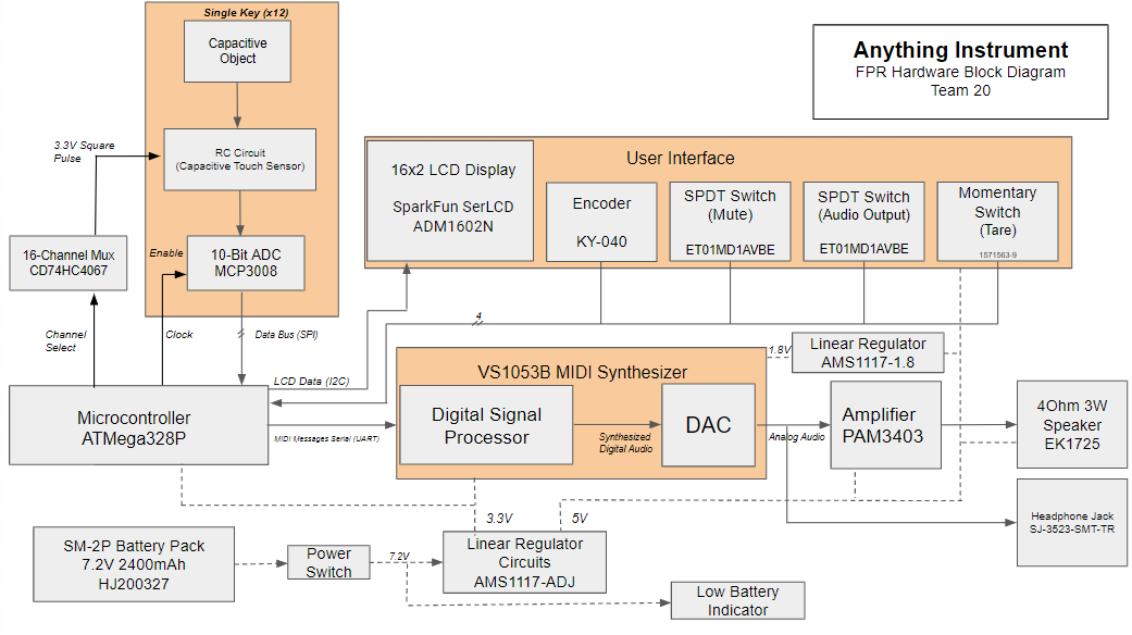
The Anything Instrument's keyboard contains 12 individual capacitive touch keys. Each of these touch sensors consist of a series RC circuit that is tuned to be most
sensitive to the average capacitance of the human body. The keyboard is designed to allow the user to play a tone on each key by first attaching a conductive object to a
key and then touching that object with bare skin.
The keyboard system continuously measures the voltage at time t = tau from a square wave source (where tau = R*C)
and checks for any significant changes from a reference value. Touching a probe between the resistor and capacitor of a key would result in that change. The reference
value can be calibrated to whatever capacitance is at that node, such as that from an apple, by using the "Tare Button" on the UI panel. This allows the user to connect
any random conductive objects to customise each key. Touching those objects further increases the capacitance at that node, triggering a "touch" response in the
microcontroller where the corresponding audio pitch is then played through a speaker.
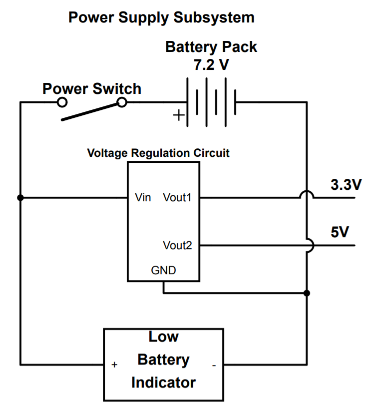
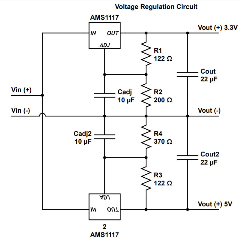
The power supply system is composed of three main parts: the battery pack and control switch, the three voltage regulation systems, and the battery status indicator system.
The power battery pack and control switch allow any rechargeable battery between 7.2V-10V with an SM-2P connection to be used to power the anything instrument. The switch allows for the battery to remain installed in the instrument while not in use to conserve power.
The voltage regulation systems regulate the battery input voltage down to 5V, 3.3V, and 1.8V. The 5V regulation system is used to power the LCD display and amplifier, while the 3.3V regulation system is used to power the microcontroller and audio synthesizer. The 1.8V output is composed of a single linear regulator running off the 5V line to power the CVDD of the audio synthesizer.
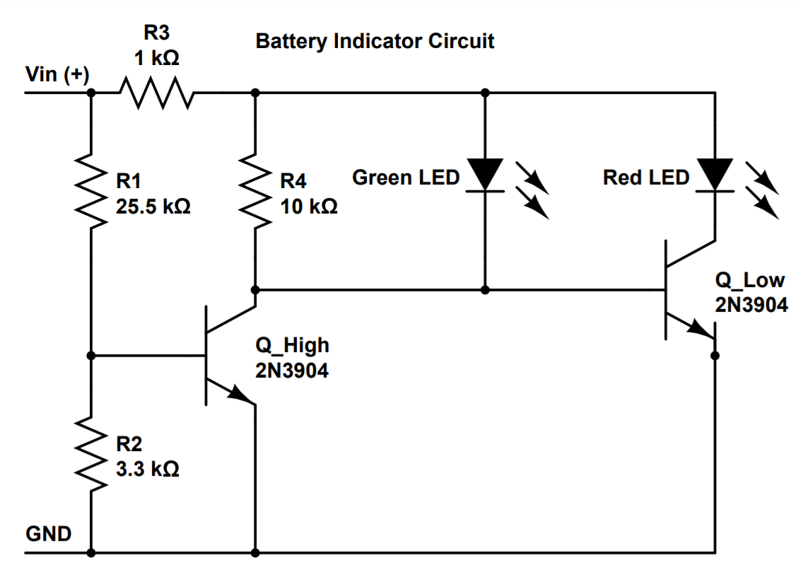
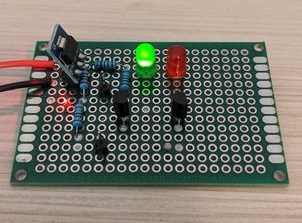
The battery indicator system is used to alert the user when the battery is charged and when it needs to be recharged. The green LED will be illuminated when the battery is above the 6.2V minimum operating voltage, and the red LED will be illuminated when the battery nears the 6.2 minimum operating voltage.

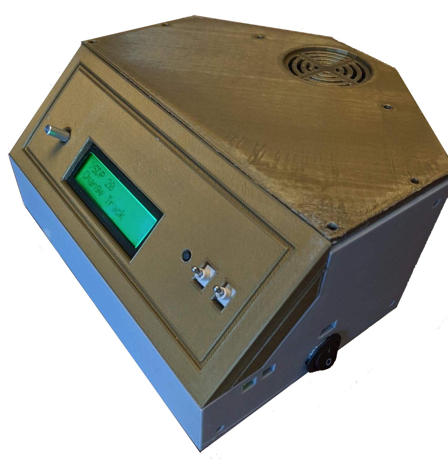
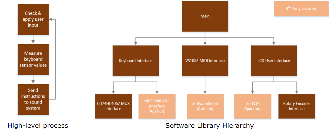
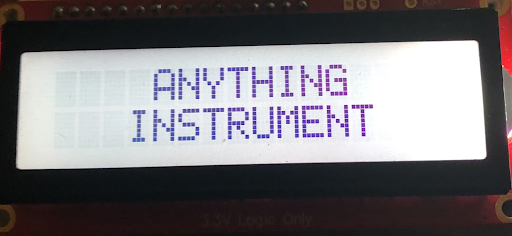
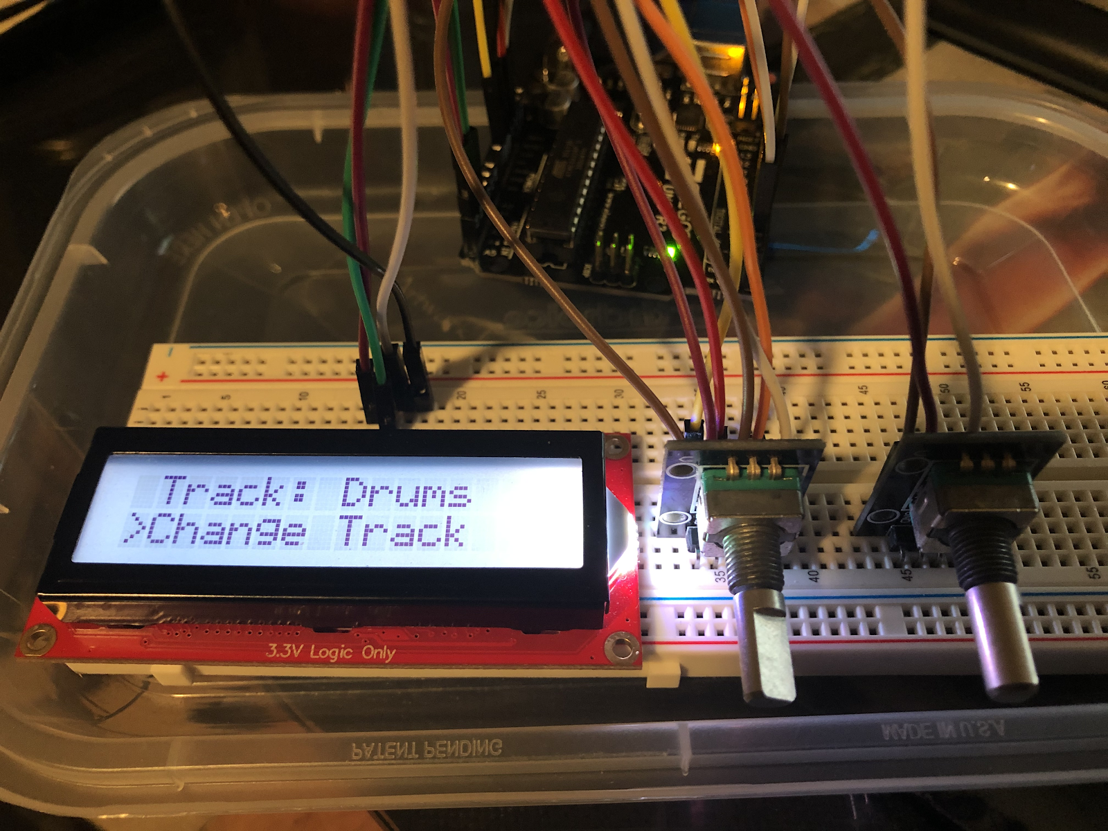
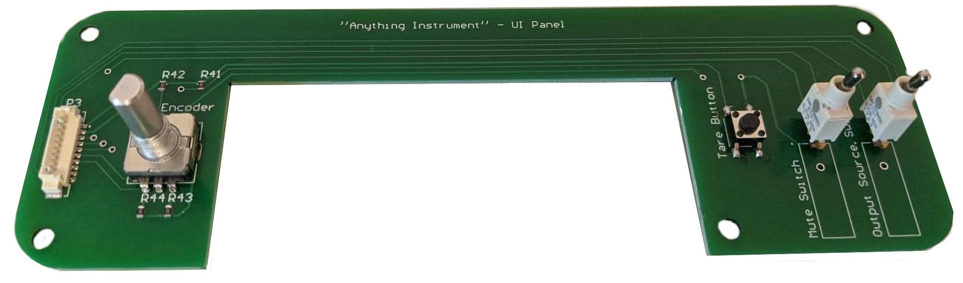
The I/O subsystem consists of a 16x2 LCD display, one rotary encoder, two SPDT switches and one momentary switch. Via I2C communication, the LCD is updated to display pertinent information such as the currently selected MIDI track and the MIDI volume level. The rotary encoder is twisted to scroll the displayed menu and depressed to make submenu selections. One SPDT switch is used to switch the audio output between the headphone jack and onboard speaker, and the other is used to disable the output of the device - a 'quick mute' switch used to suppress output during key switching and to prevent playback when desired. Lastly, the momentary switch is used to tare the capacitance of the key input subsystem.
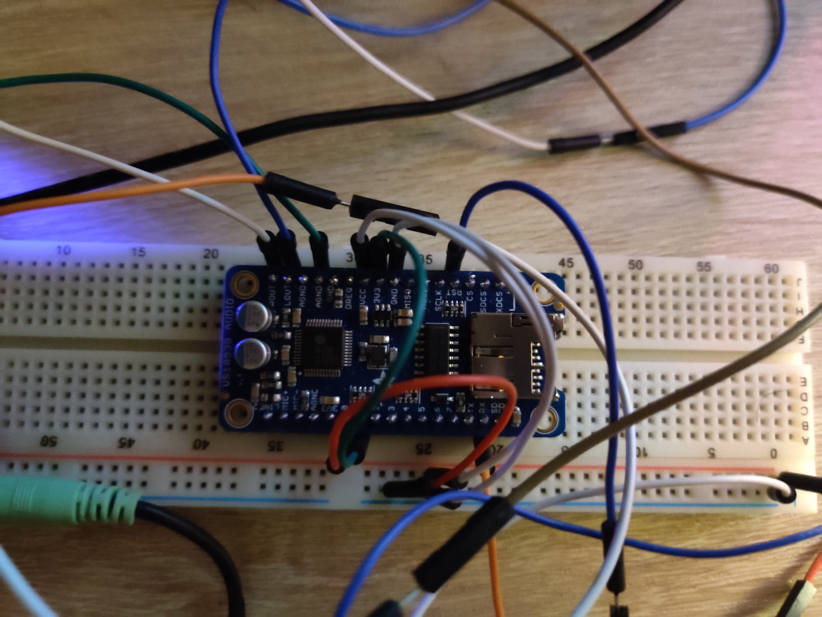
This subsystem is built on the capabilities of the VS1053B. This subsystem is responsible for sending the MIDI messages of the corresponding notes being played and playing those notes through a headphone jack. It is also responsible for adjusting the volume of the notes that are being played, as well as changing the tracks that are played.
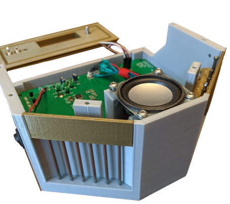
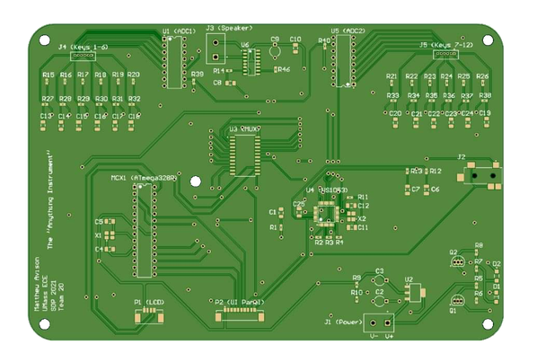
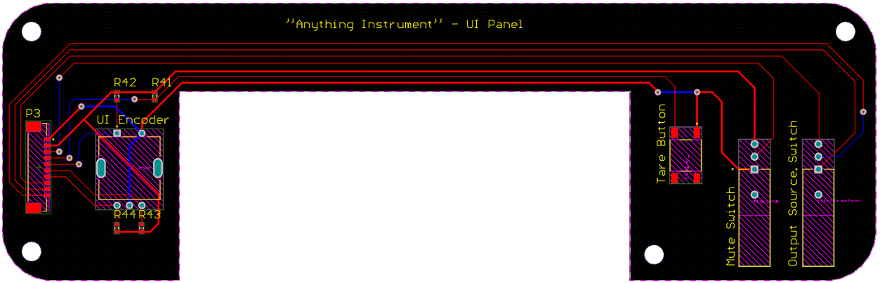
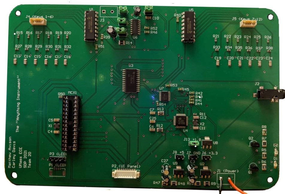
The system is housed on two main PCBs, one for the user interface and one for the motherboard. The UI hosts the user controls, while the motherboard hosts the voltage regulation system, the battery indicator circuit, the microcontroller, the midi control system, amplifier, and touch lead system.
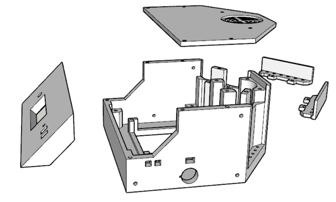
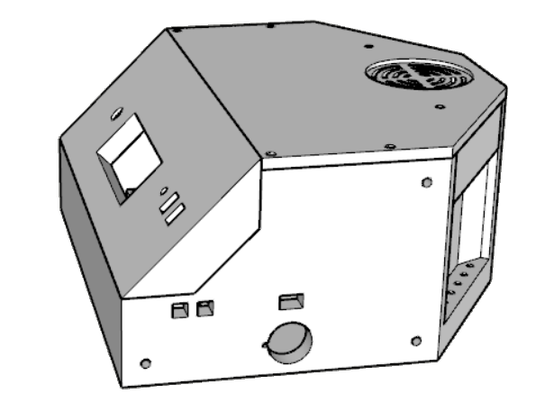
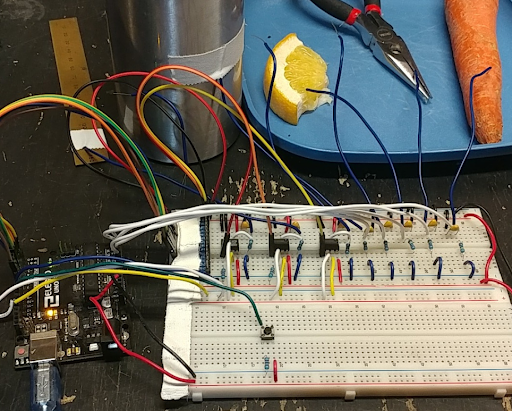
The final prototype is implemented on the custom PCBs and integrated into custom 3D printed housing to allow for an elegant and robust user expierience.
The user is able to use alagator clips connected to the 12 steel pins in the back to connect their keys, and easily naviage the user controls using a single encoder.
The tare button is located the front panel to allow for easy changes between playable objects. A mute and audio selection switch has also been implemented to allow the user to select their perferred output of headphones or the onboards speaker as well as easily mute the system when desired.