CHAPTER XVIII: ELECTROCHEMICAL METHODS
A. CONDUCTIVITY
Conductivity or specific conductance is a measure of the ability of a water to conduct electricity. It is commonly expressed in units of ohm-1cm-1, which corresponds to mho/cm. Conductivity may be used for estimating the TDS (total dissolved solids) concentration (see
Chapter XV). In addition, both of these measurements have been found to correlate well with the ionic strength, I. Ionic strength is particularly important for predicting the chemical behavior of pollutants in water treatment and in natural systems. Russell has developed the following relationship for predicting ionic strength from conductivity measurements:|
I = 1.6 x 10⁻⁵ x Specific Conductance (in µmho/cm) |
(18.1a) |
In a similar vein, the TDS has been used to estimate the ionic strength of natural waters via the Langlier approximation:
|
I ~ 2.5 x 10⁻⁵(TDS) ,where the TDS is expressed in mg/L |
(18.1b) |
Combining these two, one gets:
|
TDS ~ 0.64*K where TDS is in mg.L and K (specific conductance) is in µmho/cm |
(18.1c) |
This is exactly the value reported by Evangelou (1998) for waters dominated by chloride. He also found that sulfate-dominated waters gave higher TDS values at the same conductivity in accordance with the following model:
|
TDS ~ 0.765*K1.087, TDS in mg/L and K in µmho/cm) |
(18.1d) |
Others have reported a range of values for the ratio: TDS/K. For example, Hounslow (1995) cites 0.54 to 0.96, with 0.55 to 0.76 being most typical.
Conductivity can also be used as an indicator of the endpoint of a titration. Skoog (1985) shows some example titration curves for acid/base titrations where the endpoint occurs at a well-defined inflection point. He also shows its use with chloride analysis by addition of silver salts and precipitation of AgCl.
Table 18.1
Some Typical Solids and Conductivity Values
|
Source |
Concentration (mg/L or µmhos/cm) |
|||||
|
Low |
Avg. |
High |
||||
|
DRINKING WATERS |
||||||
|
Raw |
K |
50 |
1,000 |
|||
|
NATURAL WATERS |
||||||
|
Fresh |
TDS |
20 |
120 |
1,000 |
||
|
Brines |
K |
50,000 |
||||
|
TDS |
5,000 |
300,000 |
||||
Conductivity Meter. Theory tells us that conductivity is a function of the concentration and type of ions present, and the temperature. For a pure solution of an inorganic salt, the conductivity should be a nearly linear function of concentration. The following table shows that the conductivity per equivalent (equivalent conductance) of KCl changes little with order of magnitude changes in concentration.
The conductivity or specific conductance (K) is related to the resistance (R; in ohms) of an aqueous sample and the cell constant (C; in cm-1) of the conductivity meter.
K = C/R (18.2)
The cell constant is equal to the distance between the parallel electrodes (l) in cm divided by the cross-sectional area of the electrodes (A), in cm2 all multiplied by the efficiency.
![]() (18.3)
(18.3)
Note that most conductivity meters employ alternating current so as to avoid problems of polarization. While the electrode characteristics, l and A, may be fixed and easily determined, the electrode efficiency is known to change as the electrode ages. Thus, it should be checked each time conductivity measurements are made. This is done by running a series of standards of known conductivity, usually KCl.
Table 18.2
Conductance of KCl Standards
|
KCl |
CONDUCTANCE |
||
|
Conc. (equ/L) |
Equivalent (mmho-L/cm-equiv) |
Specific (µmho/cm) |
|
|
0.0001 N |
149.43 |
14.94 |
|
|
0.0005 N |
147.81 |
73.90 |
|
|
0.0010 N |
146.95 |
147.0 |
|
|
0.0050 N |
143.55 |
717.8 |
|
|
0.0100 N |
141.27 |
1,413 |
|
|
0.0200 N |
138.34 |
2,767 |
|
|
0.0500 N |
133.37 |
6,668 |
|
|
0.1000 N |
128.96 |
12,900 |
|
|
0.2000 N |
124.08 |
24,820 |
|
|
0.5000 N |
117.27 |
58,640 |
|
Equivalent conductance (L ) can be determined for a pure substance by dividing the specific conductance by the normality.
![]() (18.4)
(18.4)
In an ideal solution the equivalent conductance will be constant and independent of concentration. In reality, it is affected by ionic strength. The infinite dilution (or "limiting") equivalent conductance (extrapolated to I=0) can be calculated from the infinite dilution ionic conductances of the constituent ions (Table 18.3).
![]() (18.5)
(18.5)
Table 18.3
Ionic Conductances, mho-cm2/equivalent
(I=0, 25oC)
|
Cation |
|
Anion |
|
|
H+ |
349.8 |
OH- |
198.0 |
|
Na+ |
50.1 |
HCO3- |
44.5 |
|
K+ |
73.5 |
F- |
55.4 |
|
Li+ |
38.7 |
Cl- |
76.3 |
|
NH4+ |
73.4 |
Br- |
78.4 |
|
Ca+2 |
59.5 |
CH3COO- |
40.9 |
|
Mg+2 |
53.1 |
NO3- |
71.4 |
|
SO4-2 |
79.8 |
In the Environmental Engineering teaching laboratory we have a Yellow Springs Model 33 conductivity meter. This is a portable, battery-powered instrument. The probe has a cell constant of 5.0 ± 2% with platinized nickel electrodes and a low-capacitance cable. Be careful not to touch the soft platinum black coating inside the probe.
All conductivity probes will eventually become coated with scale, organic deposits, etc. When this happens the "cell test" function should alert the user (see step 7 below). The electrode may be cleaned by soaking for 5 minutes in a solution made from 10 parts distilled water, 10 parts isopropyl alcohol, and 1 part HCl. If this still does not restore proper performance, the probe will have to be re-platinized (refer to manual). It is best to store the conductivity probe in distilled water when not in use. Probes that have been stored dry should be soaked in distilled water for 24 hours prior to use.
The YSI meter is calibrated from a standard solution of 0.0100 M KCl. The following table shows the accepted conductivity values for this solution.
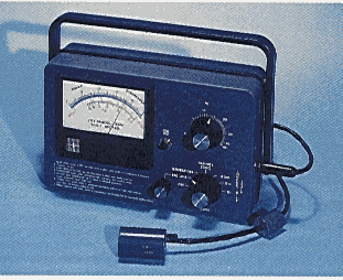
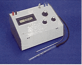
Figure 18.1 Typical field conductivity meter (YSI Model 33; left) and research-grade meter (YSI Model 32, right).
Table 18.4
Conductivity of KCl vs. Temperature
|
Temperature |
Conductivity |
Temperature |
Conductivity |
|
° C |
µmho/cm |
° C |
µmho/cm |
|
15 |
1141.5 |
23 |
1353.6 |
|
16 |
1167.5 |
24 |
1380.8 |
|
17 |
1193.6 |
25 |
1408.1 |
|
18 |
1219.9 |
26 |
1436.5 |
|
19 |
1246.4 |
27 |
1463.2 |
|
20 |
1273.0 |
28 |
1490.0 |
|
21 |
1299.7 |
29 |
1518.7 |
|
22 |
1326.6 |
30 |
1546.7 |
1. Verify that the meter needle reads zero on the conductivity scale. If it does not adjust by turning the bakelite screw on the meter face.
2. "Redline" the instrument by adjusting the Redline control so that the meter needle lines up with the red line on the meter face. If this cannot be done, replace the batteries. For acceptable accuracy use size "D" alkaline batteries, rather than zinc-carbon cells.
3. Insert the probe plug into the appropriate jack on the side of the instrument.
4. Place the probe in the solution to be measured, and provide gentle agitation.
5. Measure temperature and record this value in you notebook. Error in Model #33's temperature probe is shown in Figure 18.2.
6. Turn the mode switch to the X100 scale. If the reading is below 50 (actually <5,000 umho/cm) on the 0-500 range, switch to the X10 scale. Again, if the reading is less than 50 (actually <500 µmho/cm), switch to the X1 scale. Read the meter and multiply the number according to the scale factor. (Note: conductivity measurements are not temperature compensated.)
7. When measuring with the X10 and X100 scales, press the cell test button. If the meter falls by more than 2%, the probe is fouled, and the measurement is subject to unacceptable error. Clean the probe and re-measure. (Note: the cell test does not work on the X1 scale.) Figure 18.3 shows the conductivity error for a clean probe and instrument.
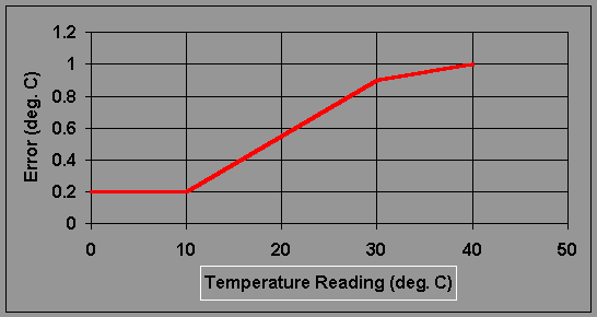
Figure 18.2
Estimated Error for the YSI Model 33: Temperature
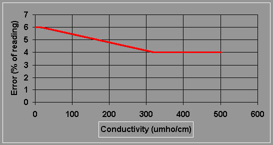
Figure 18.3 Estimated Error for the YSI Model 33: Conductivity
B. pH
1. Principle
pH is commonly measured with a potentiometric glass electrode. A reference electrode is also required. This may, however, be combined into a single probe, called a "combination pH electrode". pH electrodes always contain a bulb at the end covered with a thin glass membrane (Figure 18.4). This membrane becomes hydrated in the presence of water. Hydrogen ions can enter the silicon-oxygen structure of the glass and alter the charge. This creates a change in electrical potential with respect to the silver/silver chloride reference. The free energy change is related to the change in hydrogen ion activity by equation 18.6.
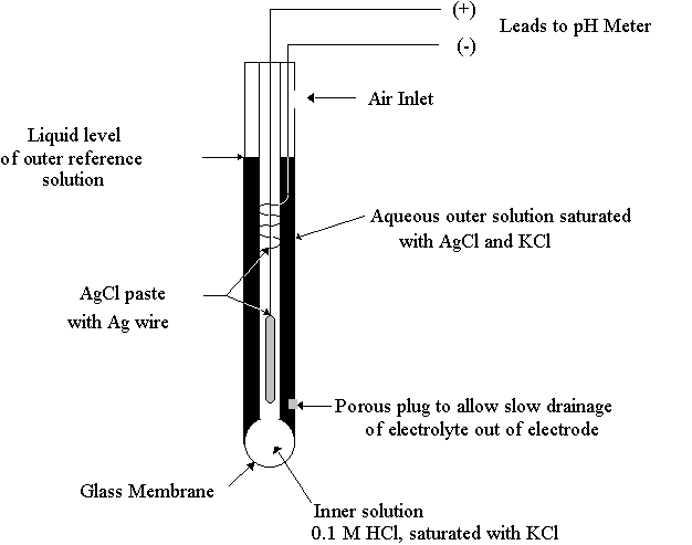
Figure 18.4
A Standard Glass Combination pH Electrode
G = -RT ln({H+}1 /{H+}2 ) (18.6)
And from this the Nerstian slope of 59.16 mV per pH unit can be derived.
-nFE = -RT ln({H+}1/{H+}2) (18.7)
![]() (18.8)
(18.8)
![]() (18.9)
(18.9)
E = L-0.05916(pH) (18.10)
Glass pH electrodes respond to hydrogen ion activity rather than concentration. Recall that activity may be expressed as the product of concentration and an activity coefficient, g .
{H+} = g H[H+] (18.11)
where the activity coefficient is a function of ionic strength and it has a value close to 1 in dilute solution. Therefore, for most applications this is not a serious disadvantage. Glass electrodes will, however, also respond to sodium ions to a slight extent. This will cause errors under conditions of low hydrogen ion activity (i.e., high pH) and high sodium concentrations.
2. Procedures
In the UMass Environmental Engineering Teaching Laboratory we use Fisher Model 140A pH Meters. These are analog meters that read either in pH or directly in millivolts of electrode potential. Each has a mirror-backed meter scale to minimize reading parallax. The repeatability is -0.05 pH (-5 mV), and the relative accuracy is -0.1 pH when measured within 2 pH units of a standardization point. The Model 140A meters are used as follows.
Start-up:
1. Adjust mechanical zero. Place function switch on standby and unplug the meter. Tilt the instrument to the normal viewing angle. If the meter pointer does not line up perfectly with pH 7.00, adjust the mechanical meter zero screw. Replug the meter.
2. Remove the electrode from its soaking solution, and slide it through one of the semi-circular slots in the electrode holder until the cap is firmly seated. Connect electrode lead in jack.
3. Carefully lower the electrode and holder assembly into a beaker until it is properly immersed in the solution (porous glass frit must be submerged), but still about 1/2 inch above the bottom. Position the small metal collar immediately below the holder and tighten. This serves as a safety stop to protect the electrode's fragile glass bulb.
4. Slip the rubber sleeve down the electrode so the fill hole is barely exposed.
Standardization (two point method):
5. With the function switch on "standby" place electrode in the pH 7 buffer, and provide mild stirring. If necessary allow several minutes for temperature equilibration. Change function switch to "pH" and adjust "calibrate" knob so that the meter reads the correct pH to within 0.01 units. Return to "standby".
6. Place the electrode in either the pH 4 or the pH 10 buffer depending on whether you're interested in having the greatest accuracy in the acid or base ranges. Switch function to "pH", and adjust the temperature knob until the meter reads the correct pH (do not re-adjust "calibrate"!).
Note: always rinse probe off with distilled water between operations; also, in order to achieve maximum precision, moderate agitation of roughly the same magnitude (i.e., same rpm of the magnetic stirring bar) must be maintained for all standards and samples.
General Operation:
7. With the function switch on "standby" place the probe in solution to be measured. Provide mild agitation, and if necessary, allow time for temperature equilibration. Switch to "pH" and record the reading. Return function switch to "standby" and remove probe from solution.
Storage:
8. Verify that function switch is on "standby". Slide rubber sleeve over fill hole. Remove probe from holder and place it in the specially sealed storage bottle (filled with pH 7 buffer).
3. pH Buffers
pH buffers are available commercially in a powdered form (to be added to distilled water) or as a prepared liquid. All of these solutions contain acids and bases whose equilibria are dependent on temperature. As a result the precise pH is also a function of temperature. For example the buffers available from VWR Scientific vary with temperature as shown in Table 18.5.
It is important to avoid streaming potential effects in dilute solutions. Therefore, such samples should be allowed to stand quiescently for several minutes before measuring (McQuaker et al., 1983; ES&T, 17:431-435).
Table 18.5
Standard Buffers
|
Actual pH |
|||||
|
Temp.(° C) |
Phthalate |
Phosphate |
Borate |
||
|
0 |
4.01 |
7.12 |
|||
|
10 |
4.00 |
7.06 |
10.15 |
||
|
20 |
4.00 |
7.02 |
10.06 |
||
|
25 |
4.00 |
7.00 |
10.00 |
||
|
30 |
4.01 |
9.96 |
|||
|
40 |
4.03 |
6.97 |
9.87 |
||
|
50 |
9.80 |
||||
|
60 |
4.09 |
6.98 |
9.73 |
||
4. Acids and Bases
Most commercially available strong acids and bases are supplied at a standard concentration as shown in Table 18.6. Unfortunately none of these concentrations are very accurate. The exact concentration as supplied by the chemical company may vary by 5% or more. Also the concentrations may change upon storage from volatilization and absorption of atmospheric moisture. Accurate determinations of acidity and alkalinity require an acid or base of known and precise concentration. In order to circumvent this problem the acid (usually hydrochloric acid) or base (usually sodium hydroxide) must first be standardized in the laboratory. This is done by conducting an acid/base titration between the titrant and a weak acid or base whichever is appropriate. There are several weak acids and bases that are available in a stable powdered form of very high purity (e.g., 99.8%). A solution of very accurate concentration can be prepared from these compounds, and it can be compared with the titrant of interest. For the standardization of hydrochloric acid we use anhydrous sodium carbonate. For the standardization of sodium hydroxide, potassium acid phthalate is generally employed.
Table 18.6
Concentrated Laboratory Acids and Bases
|
Reagent |
Molecular Weight |
% by Weight |
Molarity |
|
Acetic Acid, Glacial |
60.05 |
99.5 |
17.4 |
|
Hydrochloric Acid |
36.5 |
36 |
11.6 |
|
Nitric Acid |
63.02 |
71 |
16.0 |
|
Phosphoric Acid, Ortho |
98 |
85 |
14.7 |
|
Sulfuric Acid |
98.1 |
96 |
18.0 |
|
Ammonium Hydroxide |
17.0 |
28 (as NH3) |
14.8 |
|
Sodium Hydroxide |
40.0 |
50 |
19.1 |
C. DISSOLVED OXYGEN
Potentiometric Method. This method uses an electrode with an oxygen permeable membrane (usually polyethylene or teflon). Because the membrane severely inhibits the diffusion of ionic species to the electrodes, this method is much less susceptible to interferences than the Winkler test and its modifications. The electrode systems may be either galvanic (spontaneous reaction) or polarographic (reaction due to an applied voltage). For both systems the cathodes are of some inert metal such as silver, gold or platinum. The galvanic systems use basic anode metals such as lead, zinc or cadmium, whereas polarographic systems commonly use silver/silver chloride anodes. For a galvanic system, the cathodic reaction is:
O2 + 2 H2O + 4e- -------------> 4OH (18.12)
And the corresponding anodic reaction might be:
2Pb + 4OH- ----------------> 2PbO + 2H2O + 4e- (18.13)
Whereas, for a polarographic system, the cathodic reaction is:
O2 + 2H+ + 2e- -------------> H2O2 (18.14)
And the anodic reaction is:
2Ag + 2Cl- ----------------> 2AgCl + 2e- (18.15)
Normally the overall rate of reaction of oxygen at the electrodes (diffusion current) depends on the rate of diffusion of O2 across the membrane. Temperature is a very important variable as it strongly effects membrane permeability to oxygen. These effects can be mathematically compensated by knowing the relationship between temperature, T (degrees Kelvin), and the sensitivity, l (meter reading divided by actual D.O.):
ln(l ) = -m(1/T) + b (18.16)
where m and b are the slope and intercept of the log-reciprocal plot. Also of concern for highly saline waters is the effect of ionic strength on electrode response. It has been found that ln(l ) increases linearly with increasing ionic strength. The slope is such that a 10% increase in sensitivity occurs for every increase of 0.35 M ionic strength or 35,000 ohm-1cm-1 conductivity.
The YSI Model 54A is a polarographic system using a gold cathode, a silver anode, and a FEP teflon membrane (0.001 in). The electrolyte is KCl at half saturation, and the nominal polarizing voltage is 0.8 volts. The corresponding D.O. electrode (YSI Model #5739) contains a pressure-compensating diaphragm. This permits accurate readings at depth. It also contains a temperature sensor that feeds back and automatically corrects the D.O. reading for changing membrane permeability with changing temperature.
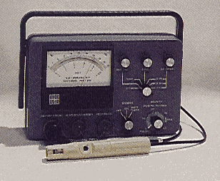
Figure 18.5 YSI Model #57 D.O. Meter and Probe
Proper calibration of the YSI Model 54A dissolved oxygen meter is as follows:
1. With the instrument off, adjust mechanical zero
2. Turn selector to "Red Line" and adjust potentiometer until the meter needle aligns with the red marking. If this is not possible, the batteries may need to be recharged.
3. Connect probe to instrument and wait for it to stabilize (up to 15 min.).
4. Turn selector to "Zero" and adjust potentiometer so that meter reads 0 mg/l.
5. Turn selector to "Temp"
Sample concentrations may simply be read by immersing the end of the probe and stirring. Adequate time must be allowed for the probe to stabilize to the new dissolved oxygen and temperature. It is recommended that the probe be left on between measurements so as to avoid the need to repolarize.
Meter accuracy is ± 0.1 mg/l. The response for 90% of the ultimate reading is 10 seconds at 30° C reducing to 30 seconds at lower temperatures.
Yellow Springs Instrument Company lists the following typical errors for the polarographic determination of dissolved oxygen:
1. The geometric mean of four general errors = 3.1%, these include:
a. Error due to meter non-linearity = 1% |
|
b. Error due to probe non-linearity = 0.3% |
|
c. Error due to the inaccuracy of the instrument thermometer during calibration = 1.5% |
|
d. Errors due to the use of a mean daily barometric pressure in estimating saturation concentration = 1.7% |
|
e. Errors in estimation of altitude (also effect calculation of saturation concentration) = 1.8% |
2. If both ranges are used, error due to inter-range tolerances = 1%
3. Error due to probe background current = abs{ Meter Reading -1}%
4. Error due to variability in the probe temperature coefficient compensating for changes in membrane permeability with temp.
|
=0%, if readings are at the same temperature as the standard |
|
|
=1%, if readings are within 5° C of the standards |
|
|
=3%, otherwise |
5. Errors in assuming 100% humidity when air calibrating the probe
|
=0.3%, at 0° C |
|
|
=0.6%, at 10° C |
|
|
=1.2%, at 20° C |
|
|
=2.1%, at 30° C. |
One must also consider:
6. Errors due to non-ideal D.O. saturation value, resulting from impurities in the water
To determine the total expected error, the geometric mean of the six must be calculated and applied to the final reading.
REFERENCES
Carritt, D.E. & J.W. Kanwisher (1959) "An Electrode System for Measuring Dissolved Oxygen", Anal. Chem., 31(1)5-9.
Evangelou, V.P. (1998) Environmental Soil and Water Chemistry: Principles and Applications, John Wiley & Sons, Inc., New York.
Hounslow, A.W. (1995) Water Quality Data: Analysis and Interpretation, CRC Lewis Publishers, New York.
Mancy, K.H. & T. Jaffee (1966) "Analysis of Dissolved Oxygen in Natural and Waste Waters", Public Health Service Publ. #999-WP-37. [Phy Sci:QD 142 M29]
Mancy, K.H., D.A. Okun & C.N. Reilley (1962) "A Galvanic Cell Oxygen Analyzer", J. of Electroan. Chem., 4:65-92
Mancy, K.H. & W.C. Westgarth (1962) "A Galvanic Cell Oxygen Analyzer", J. of Wat. Poll. Cntrl. Fed., 34(10)1037-1051.
Porges, R. (1964) "Dissolved Oxygen Determination for Field Surveys", J. Wat. Poll. Control Fed., 36:1247.
Skoog, D.A. (1985) Principles of Instrumental Analysis, 3rd edition, Saunders, Philadelphia.
PROBLEMS
Analysis of Waters in Which Calcium or Magnesium are Major Constituents:
Groundwater from Syndey, OH, April, 1952
(After: Hem, 1959)
|
Constituent |
Concentration (mg/L) |
|
Silica (SiO2)o |
18 |
|
Aluminum (Al)+3 |
trace |
|
Iron (Fe) total |
1.4 |
|
Calcium (Ca)+2 |
94 |
|
Magnesium (Mg)+2 |
40 |
|
Sodium (Na)+ |
17 |
|
Potassium (K)+ |
2.2 |
|
Bicarbonate (HCO3)- |
471 |
|
Sulfate (SO4)-2 |
49 |
|
Chloride (Cl)- |
9.0 |
|
Fluoride (F)- |
0.8 |
|
Nitrate (NO3)- |
2.4 |
|
Total Solids (measured) |
527 |
|
Total Hardness (as CaCO3) |
400 |
|
Specific Conductance (µmhos/cm) |
764 |
|
pH |
6.7 |
|
Color (Co-Pt Units) |
5 |
Hem, J.D., USGS Water Supply Paper #1473: 1sted. 1959; 2nded. 1970.