Fatigue Driving Detector


Introduction

Problem Statement

      Fatigue driving has gradually become an increasingly serious problem in recent years. Over 3,500 people lost their lives and more people get injured in accidents caused by fatigue driving every year in China. 

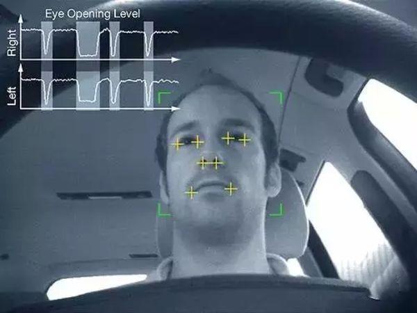
      Our “Fatigue Driving Detector” is designed to reduce fatigue driving phenomenon.It is an equipment which can warn the driver when fatigue driving is detected.

Current Products

1. Mercedes-Benz:The "Blink Monitoring" system

detects driver's blink frequency and the duration of each closed eye. 
only has a fatigue driving monitor for more than two million.


2. “SMART EYE” Company in Sweden

eye detection and facial expression detection. 
multiple cameras

Equipment

The MAXREFDES117# reference design


A low power, optical heart rate and SpO2 module complete with integrated red and IR LEDs.


This board works with both Arduino and Mbed platforms


This board can be placed on a finger (steeling wheal) to accurately detect heart rate and SpO2.value

FLORA is Adafruit's fully-featured electronics platform.


an Arduino-compatible microcontroller

has built-in USB support.

has 4 indicator LEDs

An ICSP connector for easy reprograming for advanced users.


Design
BLOCK DIAGRAM
SOFTWARE FLOWCHART

PDR

The PDR presentation in October should introduce problem statement, feasibility analysis, design alternative(including system-level block diagram) and proposed MDR prototype of the project.

The team should make corresponding adjustments according to the suggestions of the advisor and Faculty Review Board.

Files Download

MDR

The MDR presentation at the end of fall semester should show both the hardware and software prototypes which can prove that the chosen design path is likely to lead to a completed project in April.

CDR

The CDR presentation should show the prototype of the project, which has all the main features of the final product.

Files Download

FDR

The CDR presentation should show the prototype of the project, which has all the main features of the final product.

Files Download
Outcome
      The result of the SpO2 system has 4 parts, which are HR, HRvalid, SPO2, SPO2Valid. The first column HR is heart rate value, the third column SPO2 is SpO2 value, and the second and forth column show the validities of heart rate and SpO2. 
      The left picture shows the result when tester’s finger is not attached to the sensor, HRvalid and SPO2Valid is 0, which means heart rate value and SpO2 value is unavailable, and the value is -999. 
      The right picture shows the result when tester’s finger is attached to the sensor, HRvalid and SPO2Valid is 1, which means heart rate value and SpO2 value is available. 

Demo


Team

Arman Pouraghily

Adviser

Department of Electrical and Computer Engineering

University of Massachusetts
Jiong Wang(jiongwang@umass.edu)
Graduate student in Electrical and Computer Engineering,expected to graduate in May 2020.
Work as the team leader and hardware designer.
Yachen Liu(yachenliu@engin.umass.edu)
Graduate student in Electrical and Computer Engineering,expected to graduate in May 2020.
Work as software designer.
Hongyu Ba(hba@umass.edu)
Graduate student in Electrical and Computer Engineering,expected to graduate in May 2020.
Work as the hardware designer.