Concurrent Error Detection in ALU's by
Recomputing with Shifted Operands
This is a help file for RESO (Re-computing
with Shifted Operands) simulator. This simulator is created by using Java.
Introduction
There were many methods of concurrent error detection
in the Arithmetic and Logic Units (ALU's). However, some of those
methods such as AN code, Residue Code, Inverse Residue code have
limitations, they can't be used for checking logical operation.
"Re-computing with Shifted Operands"(RESO) is one
of methods of concurrent error detection. RESO can detect errors in both
the arithmetic and logic operations. RESO uses the principle of time redundancy
in detecting the errors and achieves its error detection capability through
the use of the already existing replicated hardware in the form of identical
bit slices. Here is a conceptual diagram of RESO.
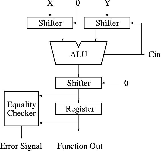
During the first step, three shifters don't
shift the data, therefore the input and output of shifter is same. During
the second step, the first two left-shifter shift input data by "K"
bits and the right-shifter shifts input data by "K" bits.
Here is simple block diagram of a bit-slice of
ALU. In this diagram, FA(Full-Adder) is a ripple carry adder.
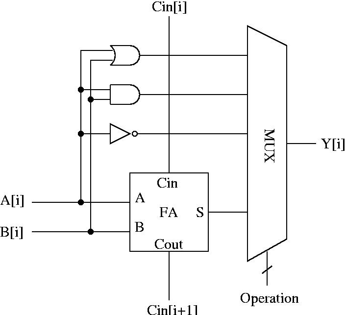
The fault model used is more general than the commonly
assumed stuck-at fault model. This fault model assumes that the faults
are confined to a small area of the circuit and that the precise nature
of the faults is not known. This means the faulty sum and the faulty carry
bits can have any logical values at any time. This model is very appropriate for the VLSI
circuits.
In upper diagram, Cin[i+1] or Y[i] or both can
be faulty, you can modeling this situation by using 2 fields of RESO simulator,
faulty_bits(carry), faulty_bits(out).
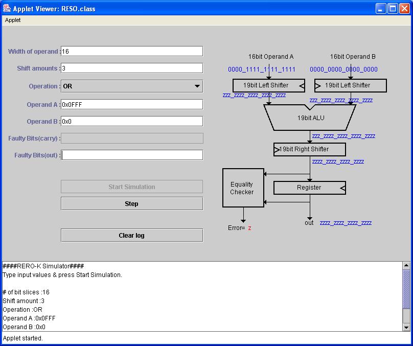
Usage
1. "Width of operand": Default value of this field is 16 bits. This
means that input A or B value can be from 0xFFFF to 0x0000.
2. "Shift amount" : Default value of this field is 3 bits. This
means that input A will be shifted by 3 bit. If A is 0x0001, shifted value
will be 0x0008.
3. "Operation" : Default value of this field is OR. You can select
OR, AND, NOT, and ADD.
4. "Operand A" & "Operand B": These are input values of this simulation.
5. "Faulty Bits(carry & out)" : By using this field, you
can specify faulty bits. If you set "Fault Bits(out)" as
"0 1", this means that bit 0 and 1 is faulty and each bit can be stuck at High or Low.
6. "Start Simulation" & "Step" : By using these buttons, you can
run simulation.
7. "Clear Log": By using this button, you can clear
the logs.
Theorems
RESO-k has the following error detection capabilities in
an ALU:
1) detects all errors in all bit-wise logical operations when
the failure are confined to k adjacent bit-slices,
2) detects all errors
in arithmetic operations in a ripple carry adder when the failure are confined
to (k-1) adjacent bit-slices for k>1.
Undetectable Fault Example
Width of operand:16
Shift amounts:3
Operation: ADD
Operand
A: 0x0FFF
Operand B: 0x0
Faulty bits(carry): 0 1 2
Faulty bits(out):
0 1 2
If you simulate these conditions, you may realize there are
some undetectable faults. So I explained one undetectable fault example
at here.
During un-shifted first stage, result should be 0x0FFF,
but some combination of faulty situation will generate 0x1000.
|
|
0
|
0
|
0
|
0
|
0
|
0
|
0
|
1
|
1
|
1
|
1
|
1
|
1
|
1
|
1
|
1
|
1
|
1
|
1
|
|
+
|
0
|
0
|
0
|
0
|
0
|
0
|
0
|
0
|
0
|
0
|
0
|
0
|
0
|
0
|
0
|
0
|
0
|
0
|
0
|
|
|
0
|
0
|
0
|
0
|
0
|
0
|
1
|
0
|
0
|
0
|
0
|
0
|
0
|
0
|
0
|
0
|
0
|
0
|
0
|
This will be happen in this situation: S0=0, S1=0, S2=0,
C0=1, C1=1, C2=1.
During shifted second stage, result should be 0x7FF8, but
some combination of faulty situation will generate 0x8000.
|
|
0
|
0
|
0
|
0
|
1
|
1
|
1
|
1
|
1
|
1
|
1
|
1
|
1
|
1
|
1
|
1
|
0
|
0
|
0
|
|
+
|
0
|
0
|
0
|
0
|
0
|
0
|
0
|
0
|
0
|
0
|
0
|
0
|
0
|
0
|
0
|
0
|
0
|
0
|
0
|
|
|
0
|
0
|
0
|
1
|
0
|
0
|
0
|
0
|
0
|
0
|
0
|
0
|
0
|
0
|
0
|
0
|
0
|
0
|
0
|
This will be happen in this situation: S0=0, S1=0, S2=0,
C0=0, C1=0, C2=1. After right shift, the result will be 0x1000. This means
RESO-3 can't detect some fault in 3 bit faulty situation
.