Introduction
From "Concurrent Error Detection in ALU's by Recomputing with Shifted Operands", Janak H. Patel and Leona Y. Fung."One well-known time redundancy method is called "Re-computing with Shifted Operands by k-bit" (RESO-k). All operations are done twice, once with the normal operands, and once with the operands shifted by k bits. This method can detect k consecutive logic errors and (k-1) arithmetic errors; however, when an n-bit operand is shifted left by k bits, its leftmost k bits move out, To preserve these bits during the re-computation step, an (n+k)-bit Arithmetic Logic Unit (ALU) and several (n+k)-bit shifters are needed. Furthermore, since the length of the ALU has increased to (n+k) bits, the re-computation takes (n+k)-bit operations rather than n-bit operations. As k becomes larger, a considerable increase of space and time complexity occurs, and the error probability in the ALU increases also.""Recomputing with Rotated Operands"(RERO) is one of methods of concurrent error detection. RERO was designed to overcome the limit of RESO. RERO re-computes rotated operand instead of shifted operand. Here is a conceptual diagram of RERO.
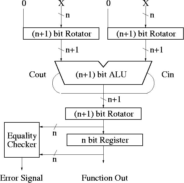
During the first step, three rotators don't shift the data, therefore the input and output of rotator is same. During the second step, the first two left-rotator rotate input data by "K" bits and the right-rotator rotates input data by "K" bits.
The fault model used is the same model of RESO.